Design emergency relief systems for runaway exothermic reactions using DIERS methodology, two-phase flow venting, adiabatic calorimetry data, and API 520 Part II requirements.
Runaway reactions occur when exothermic reactions lose temperature control, causing self-accelerating temperature rise that can lead to overpressure, vessel rupture, and catastrophic release. Emergency relief systems provide the final layer of protection.
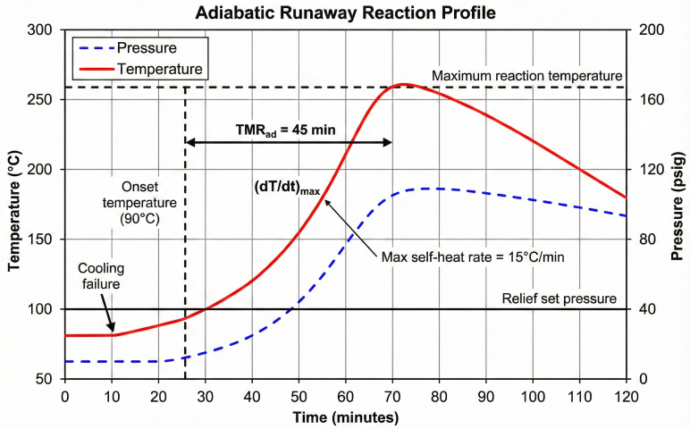
Figure 1: Adiabatic runaway reaction temperature and pressure profile showing onset, TMRad, and maximum rate.
Batch reactors
Polymerization, nitration
Exothermic batch processes in pharmaceutical and specialty chemical production.
Semi-batch reactors
Slow addition reactions
Reagent accumulation leads to runaway if cooling fails during addition.
Continuous reactors
CSTR, tubular
Cooling loss or flow upsets cause temperature excursions.
Safety instrumented system (SIS): High-high temperature trip to close feed, open emergency cooling, dump to catch tank
Emergency relief (PSV or rupture disk): Vent excess vapor/liquid to containment system when pressure exceeds set point
Why runaway relief is challenging: Unlike simple overpressure (blocked outlet, external fire), runaway reactions involve coupled thermal-hydraulic phenomena: heat generation increases with temperature (Arrhenius kinetics), vapor generation can be tempered (vapor-only) or gassy (two-phase), and relief changes system pressure affecting boiling point. DIERS (Design Institute for Emergency Relief Systems) developed systematic methodology to address these complexities.
2. Adiabatic Calorimetry Testing
Adiabatic calorimetry measures heat release rate (dT/dt) and pressure rise rate (dP/dt) during runaway reactions under near-adiabatic conditions. This data is essential for DIERS vent sizing.
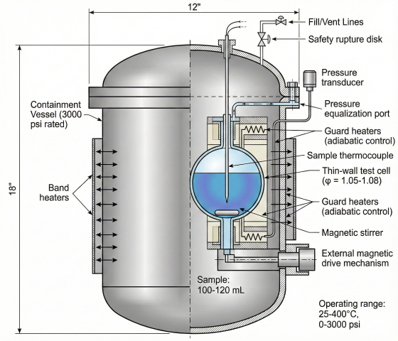
Figure 2: VSP2 adiabatic calorimeter cross-section showing test cell, containment vessel, and instrumentation.
Calorimetry Instruments
Instrument
Sample
φ-Factor
Primary Use
ARC
5-10 mL
1.05-1.20
Screening, TMRad determination
VSP2
100-130 mL
1.04-1.08
DIERS vent sizing, system classification
RSST
10 mL
~1.2
Quick screening, gas generation rate
Phi-TEC II
50-100 mL
1.02-1.05
Low φ tests, accurate T-P data
Phi-Factor (φ) Correction
Thermal Inertia Correction:
φ = (m_sample × Cp_sample + m_bomb × Cp_bomb) / (m_sample × Cp_sample)
Where:
φ = Phi-factor (dimensionless, φ ≥ 1.0)
m_sample = Mass of reactant sample
Cp_sample = Heat capacity of sample
m_bomb = Mass of test cell (stainless steel)
Cp_bomb = Heat capacity of test cell
For adiabatic conditions, φ = 1.0 (no thermal inertia).
For VSP2 with 130 mL cell, typical φ = 1.05-1.08.
Temperature Correction:
dT/dt (φ=1) = φ × dT/dt (measured)
T_final (φ=1) = T_initial + φ × (T_final,measured - T_initial)
Higher φ means measured temperature rise is lower than true adiabatic case.
Corrected data represents full-scale reactor behavior.
Key Parameters from Calorimetry
1. Self-Heat Rate (dT/dt)
dT/dt = Heat generation rate / (m × Cp) (°C/min or K/min)
Arrhenius behavior:
dT/dt = A × exp(-E/RT)
Where:
A = Pre-exponential factor
E = Activation energy (J/mol)
R = Gas constant (8.314 J/mol·K)
T = Absolute temperature (K)
Typical criteria:
dT/dt < 0.1 K/min → Reaction under control
dT/dt > 1 K/min → Potential runaway
dT/dt > 10 K/min → Severe runaway, rapid pressure rise
2. Time to Maximum Rate (TMRad)
TMRad (Time to Maximum Rate under adiabatic conditions):
TMRad = (T_final - T_initial) / (dT/dt)_max
At temperature T, time to reach maximum rate:
TMRad(T) ≈ integral from T to T_max of dT/(dT/dt)
Safety criterion:
TMRad > 24 hours at maximum storage/process temperature → Acceptable
TMRad < 8 hours → Requires risk mitigation (lower temp, smaller batches, cooling)
Example:
T_process = 80°C, TMRad(80°C) = 12 hours
If cooling fails, 12 hours available before runaway reaches maximum rate.
Sufficient time for operator intervention or SIS to trip process.
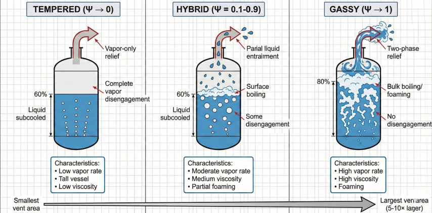
Gassy (two-phase): High vapor rate, bulk boiling throughout liquid, two-phase foam/churn vents
Calorimetry best practices: Test at actual process composition and concentration. Use heat-wait-search mode to detect low-temperature onset. Run multiple tests at different fill levels (50%, 70%, 90%) to characterize vapor disengagement. Report φ-corrected data for DIERS calculations.
3. DIERS Methodology
DIERS (Design Institute for Emergency Relief Systems) developed a rigorous methodology for sizing relief vents for runaway reactions, published in AIChE DIERS Project Manual (1992).
Figure 3: DIERS system classification showing tempered, hybrid, and gassy flow patterns during emergency relief.
System Classification
Systems are classified based on vapor-liquid behavior during relief:
Required Vent Area (DIERS):
A = (m_0 / G) × √(Cp × dT/dt × φ / ΔH_v)
Where:
A = Vent area (in²)
m_0 = Initial liquid mass in reactor (lb)
G = Two-phase mass flux (lb/s·in²)
Cp = Liquid heat capacity (Btu/lb·°F)
dT/dt = Self-heat rate at relief pressure (°F/s)
φ = Phi-factor from calorimetry
ΔH_v = Effective latent heat (Btu/lb)
Two-Phase Mass Flux (G):
For tempered system (Ψ → 0):
G = √(2 g_c ρ_V ΔP) (vapor flow)
For gassy system (Ψ = 1):
G = √(2 g_c ρ_L ΔP / (1 + L)) (HEM)
Where:
L = v_fg / v_f × (Cp ΔT_sub / ΔH_v) (quality parameter)
v_fg = Specific volume change on vaporization
v_f = Liquid specific volume
ΔT_sub = Subcooling
For hybrid system:
Interpolate between tempered and gassy using Ψ.
Leung Omega Method (Simplified DIERS)
Leung developed a simplified correlation for DIERS vent sizing:
Leung Omega Method:
A = (Q_s / C) × √(ω / P_s)
Where:
Q_s = Volumetric flow rate at relief (ft³/s)
C = Discharge coefficient (0.6-0.7 for rupture disk, 0.3-0.5 for PSV)
ω = Homogeneous two-phase flow parameter
P_s = Relief set pressure (psia)
ω = f(reduced pressure P_r, quality χ)
For low-quality two-phase flow (χ < 0.1):
ω ≈ 1 + χ × (ρ_L/ρ_V - 1)
This method is widely used in commercial software (SuperChems, RELIEF).
DIERS key insight: Two-phase venting is governed by liquid density, not vapor density. Even though vapor is flowing, the high liquid content in churn-turbulent flow means the effective density is close to liquid density → much lower velocity through vent → larger vent area required (often 5-10× larger than vapor-only case).
4. Two-Phase Flow Venting
Two-phase venting occurs when vapor generation rate is so high that liquid and vapor discharge together through the relief vent. Proper characterization and sizing prevents vessel overpressure.
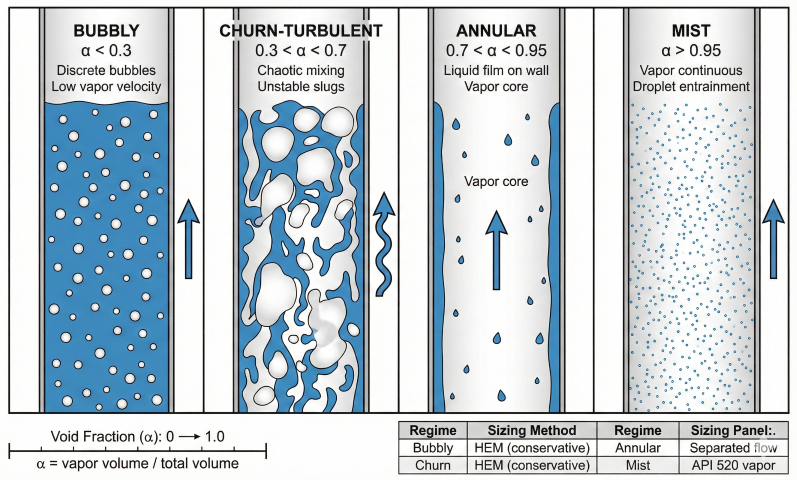
Figure 4: Two-phase flow regimes in vertical relief piping with void fraction ranges and sizing methods.
Flow Regimes During Venting
Regime
Description
Void Fraction (α)
Vent Sizing
Bubbly flow
Discrete bubbles in continuous liquid
α < 0.3
HEM (homogeneous)
Churn-turbulent flow
Chaotic mixing, large unstable bubbles
0.3 < α < 0.7
HEM (conservative)
Annular flow
Liquid film on walls, vapor core
α > 0.7
Separated flow models
Mist flow
Liquid droplets in vapor
α > 0.95
API 520 vapor with entrainment
Homogeneous Equilibrium Model (HEM)
HEM Assumptions:
1. Vapor and liquid travel at same velocity (no slip)
2. Thermodynamic equilibrium at all points
3. Isentropic expansion through vent
Critical Flow (Choked):
G_crit = √(ρ_m × (dP/dv)_s)
Where:
G_crit = Critical mass flux (lb/s·ft²)
ρ_m = Mixture density = ρ_L (1-α) + ρ_V α
α = Void fraction (vapor volume fraction)
(dP/dv)_s = Slope of isentrope on P-v diagram
For two-phase mixture:
(dP/dv)_s ≈ -P / [(1-χ)v_f + χ v_g]
Where χ = vapor mass fraction (quality)
Required Vent Area:
A = W / (C × G_crit)
Where:
W = Required mass relief rate (lb/s)
C = Discharge coefficient (0.6-0.7 rupture disk, 0.3-0.5 PSV)
G_crit = Critical mass flux from above
Typical result:
Two-phase venting requires 3-10× larger area than vapor-only.
Vapor Disengagement (Hybrid Systems)
In hybrid systems, some vapor separates from liquid and vents as vapor-only flow. Disengagement reduces required vent area compared to fully gassy (HEM) case.
Rupture disk: Preferred for two-phase, full-bore opening, no chatter, higher C (0.6-0.7), one-time use
Balanced bellows PSV: Reusable, may chatter in two-phase service, lower C (0.3-0.5), requires larger orifice
Combination: Rupture disk upstream of PSV protects PSV from corrosive/fouling fluids
2. Quench/Catch Tank
Catch Tank Sizing:
V_tank = V_reactor × f_discharge + V_freeboard
Where:
V_reactor = Reactor liquid volume
f_discharge = Fraction discharged during relief (0.5-0.9 typical)
V_freeboard = Vapor space to prevent tank overfill (20-30% of total volume)
Example:
2000-gal reactor, 80% full → 1600 gal liquid
Assume 70% discharges during relief → 1120 gal
Freeboard 25% → total catch tank volume = 1120 / 0.75 = 1500 gal minimum
Catch tank must withstand:
- Thermal shock from hot discharge (200-300°F liquid)
- Pressure rise from vapor generation (size vent on catch tank)
- Corrosive/reactive chemicals (material selection)
3. Scrubber/Separator
If relieving to flare or atmosphere, install knockout drum to separate liquid from vapor:
Gravity separator: Size for Stokes settling velocity (V_term = d_p² × g × Δρ / 18μ)
Cyclone separator: Compact, high efficiency, 5-10 psi pressure drop
Mesh pad demister: Capture fine droplets (> 10 micron), low pressure drop (< 1 psi)
Two-phase venting system design: Use adiabatic calorimetry (VSP2, Phi-TEC) to measure dT/dt and dP/dt during runaway. Classify system as tempered/hybrid/gassy based on Ψ parameter. Size vent using DIERS or Leung omega method for two-phase flow. Install rupture disk (not PSV) for gassy systems. Route to catch tank or separator before flare.
5. Relief Vent Sizing Examples
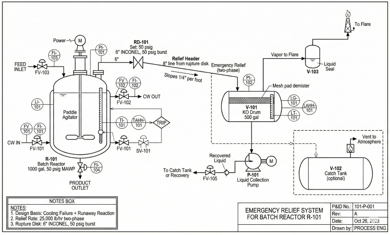
Figure 5: Emergency relief system P&ID showing reactor, rupture disk, knockout drum, and flare routing.
Example 1: Tempered System (Vapor-Only)
Scenario:
Batch reactor, exothermic polymerization with reflux condenser
Runaway scenario: Loss of cooling water, reflux condenser fails
Reactor: 2000 gal (7.57 m³), 70% fill, P_set = 50 psig
Calorimetry Data (VSP2):
dT/dt (at 50 psig) = 5 K/min = 0.083 K/s
φ = 1.06
Cp = 2.5 kJ/kg·K = 0.60 Btu/lb·°F
ΔH_vap = 400 kJ/kg = 172 Btu/lb
Liquid density ρ_L = 900 kg/m³ = 56.2 lb/ft³
Vapor density ρ_V (at 50 psig, 180°C) = 3.5 kg/m³ = 0.22 lb/ft³
System classification: Ψ < 0.1 (low viscosity, tall vessel, good disengagement)
→ TEMPERED, use API 520 vapor relief
Required Vapor Relief Rate:
Heat generation rate:
Q_gen = m × Cp × (dT/dt) × φ
m = 7.57 m³ × 0.7 fill × 900 kg/m³ = 4780 kg
Q_gen = 4780 × 2.5 × 0.083 × 1.06 = 1050 kW = 3.58 MMBtu/hr
Vapor generation rate:
W_vapor = Q_gen / ΔH_vap = 1050 / 400 = 2.63 kg/s = 20,900 lb/hr
API 520 Vapor Orifice Sizing:
A = W / (C × K_d × K_b × K_c × P × √(M/TZ)) (API 520 Equation 7)
Assume:
C = 315 (constant for US units, k ≈ 1.0)
K_d = 0.975 (discharge coefficient, conventional PSV)
K_b = 1.0 (backpressure correction, low backpressure)
K_c = 1.0 (combination correction factor)
P = 50 + 10% overpressure = 55 psig = 69.7 psia
M = 50 (average molecular weight of vapors)
T = 180°C = 453 K = 816°R
Z = 0.96
A = 20,900 / (315 × 0.975 × 1.0 × 1.0 × 69.7 × √(50/(816×0.96)))
A = 20,900 / (315 × 0.975 × 69.7 × 0.253)
A = 20,900 / 5409
A = 3.86 in²
Select standard orifice: N (4.34 in²) per API 526
Actual orifice: 2.5" diameter (A = 4.91 in²) provides 27% margin
Example 2: Gassy System (Two-Phase)
Scenario:
Batch reactor, nitration reaction with gas evolution (NO₂)
Runaway scenario: Cooling failure + rapid decomposition
Reactor: 1000 gal (3.79 m³), 80% fill, P_set = 30 psig
Calorimetry Data (VSP2):
dT/dt (at 30 psig) = 15 K/min = 0.25 K/s (rapid runaway)
dP/dt = 120 psi/min = 2.0 psi/s (high gas generation)
φ = 1.05
Cp = 3.0 kJ/kg·K
ΔH_vap = 350 kJ/kg
ρ_L = 1100 kg/m³ = 68.7 lb/ft³
μ = 50 cP (high viscosity, polymer solution)
System classification: Ψ = 0.95 (high viscosity, high gas rate, foaming)
→ GASSY, use HEM two-phase model
DIERS Vent Sizing:
m_0 = 3.79 m³ × 0.8 × 1100 kg/m³ = 3330 kg = 7340 lb
Self-heat rate:
q = Cp × (dT/dt) × φ = 3000 × 0.25 × 1.05 = 788 J/kg·s = 0.34 Btu/lb·s
Two-phase mass flux (HEM):
G = √(2 × g_c × ρ_L × ΔP / (1 + L))
Assume L ≈ 0.1 (low quality, mostly liquid):
ΔP = 10% overpressure = 0.1 × 30 = 3 psi = 432 lb/ft²
G = √(2 × 32.2 × 68.7 × 432 / 1.1)
G = √(1.74 × 10⁶)
G = 1318 lb/s·ft² = 9.15 lb/s·in²
Required vent area:
A = (m_0 / G) × √(q / ΔH_v)
ΔH_v = 350 kJ/kg = 150 Btu/lb
A = (7340 / 9.15) × √(0.34 / 150)
A = 802 × 0.0476
A = 38.2 in²
With discharge coefficient C = 0.65 (rupture disk):
A_actual = 38.2 / 0.65 = 58.7 in²
Select 9" rupture disk (A = 63.6 in²) — 8" (50.3 in²) is now inadequate
Use 9" disk (~8% margin)
Comparison:
If sized as vapor-only (tempered), would get A ≈ 5-7 in² → 8-10× undersized!
Two-phase relief requires much larger vent due to low mixture velocity.
Vent panel sizing for dust explosions, not runaway reactions
CCPS Guidelines
Chemical Process Safety (CCPS)
Inherently safer design, layers of protection analysis (LOPA)
Software Tools for Vent Sizing
SuperChems (DIERS-licensed): Complete DIERS methodology, tempered/hybrid/gassy sizing, VSP data import
Aspen HYSYS RELIEF: API 520 and DIERS methods integrated with process simulation
PRO/II SAFIRE: Safety analysis and relief sizing with rigorous thermodynamics
FauRe SAFIRE: Standalone DIERS tool with extensive thermodynamic database
Vent sizing workflow: (1) Perform adiabatic calorimetry testing (VSP2, ARC, RSST). (2) Classify system as tempered/hybrid/gassy based on Ψ parameter or observation. (3) For tempered, use API 520 vapor sizing. For hybrid/gassy, use DIERS or Leung omega method. (4) Apply 20-30% safety margin. (5) Verify with dynamic simulation if critical (high-risk scenarios). (6) Design containment system (catch tank, scrubber) sized for total discharge.
Runaway reaction relief is the emergency venting of a reactor when an exothermic reaction becomes uncontrolled, requiring properly sized relief devices to prevent vessel rupture.
What is the DIERS methodology?+
DIERS (Design Institute for Emergency Relief Systems) provides methods for sizing emergency relief systems that account for two-phase vapor-liquid flow during runaway reactions.
What standard covers reaction relief vent sizing?+
API 520 Part II provides guidance on emergency relief system design for reactors, including two-phase venting calculations.