1. Heat Transfer Fundamentals
Heat exchangers transfer thermal energy between fluids at different temperatures. The heat transfer rate depends on three mechanisms acting in series:
Conduction
Through walls
Heat flows through tube walls separating hot and cold fluids.
Convection
Film coefficients
Hot-side hh and cold-side hc control fluid-to-wall transfer.
Fouling
Resistance buildup
Deposits reduce U over time; design includes fouling margins per TEMA.
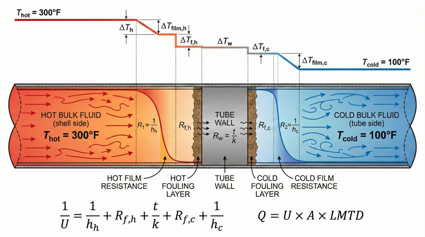
Fundamental Heat Transfer Equation
Overall Heat Transfer Coefficient (U)
U combines all resistances in series—hot-side film, tube wall, cold-side film, and fouling:
Typical Overall U Values
| Service | U Clean | U Design |
|---|---|---|
| Water to water | 200–250 | 150–200 |
| Water to light oil | 80–120 | 60–90 |
| Light oil to light oil | 60–90 | 40–60 |
| Heavy oil to heavy oil | 30–50 | 20–35 |
| Gas to gas (no fins) | 10–30 | 8–25 |
| Condensing steam to water | 400–600 | 300–500 |
Units: BTU/hr·ft²·°F. Design U includes fouling allowance per TEMA.
2. Log Mean Temperature Difference (LMTD)
LMTD represents the effective temperature driving force when terminal temperatures vary along the exchanger length. It accounts for the logarithmic temperature profile in heat exchangers.
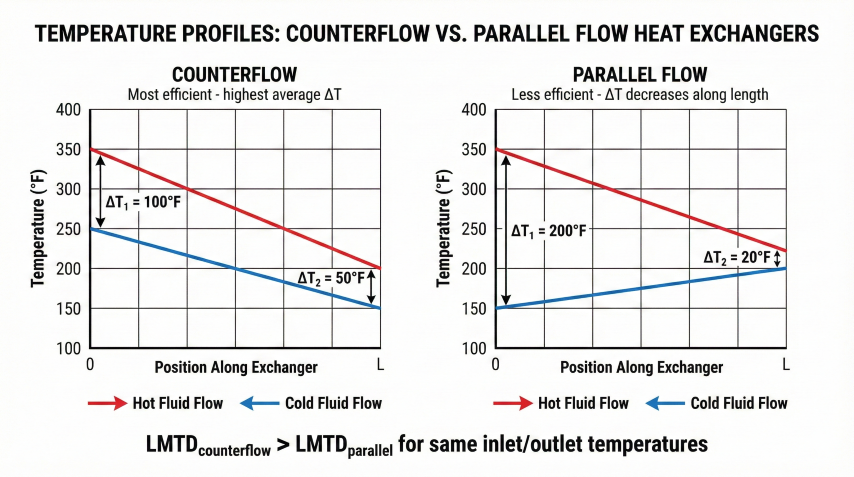
Counterflow Configuration
Most efficient arrangement—hot fluid enters where cold fluid exits, maximizing ΔT at both ends.
LMTD Correction Factor (F)
For shell-and-tube exchangers with multiple passes, actual mean ΔT is lower than pure counterflow. The F factor corrects for this:
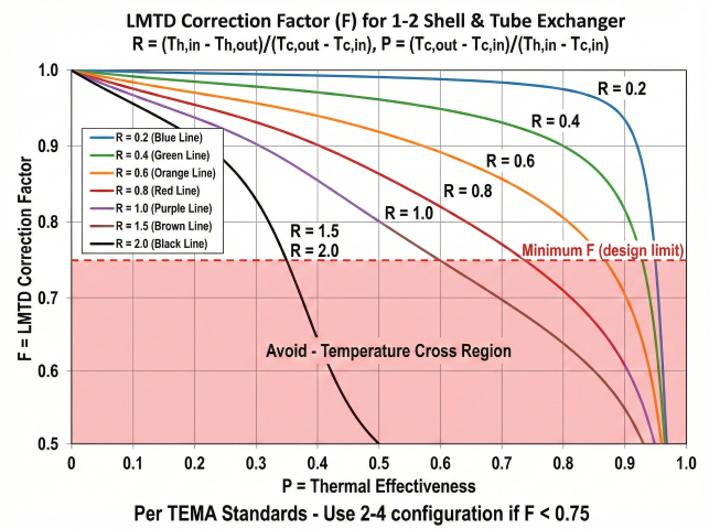
F Factor Guidelines
| Configuration | F Range | Comments |
|---|---|---|
| True counterflow | 1.0 | Maximum effectiveness |
| 1-2 shell & tube | 0.75–0.95 | Most common; avoid F < 0.75 |
| 2-4 shell & tube | 0.85–0.98 | Higher F but more expensive |
| Crossflow (air-cooled) | 0.70–0.90 | Lower due to flow pattern |
Example Calculation
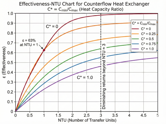
3. Effectiveness-NTU Method
Alternative to LMTD when outlet temperatures are unknown. Essential for rating existing exchangers or iterative design optimization.
Thermal Effectiveness (ε)
Number of Transfer Units (NTU)
Heat Capacity Ratio (C*)
Effectiveness Correlations
Counterflow
Parallel Flow
Phase Change (C* = 0)
When to Use Each Method
| Situation | Method | Reason |
|---|---|---|
| All 4 temperatures known | LMTD | Simpler calculation |
| Outlet temps unknown | ε-NTU | Direct solution |
| Rating existing exchanger | ε-NTU | Given area, find outlets |
| Phase change process | ε-NTU | C* = 0 simplifies equations |
4. Shell-and-Tube Design
Shell-and-tube exchangers are the workhorse of process industries—robust, repairable, and scalable to very large duties.
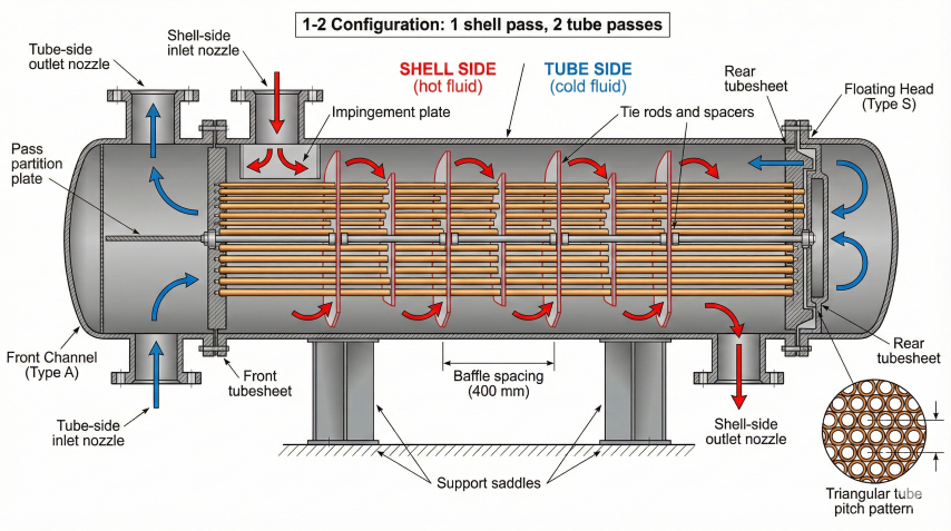
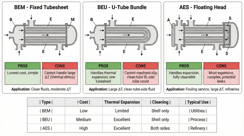
TEMA Nomenclature
Exchangers are designated by three letters: Front Head - Shell Type - Rear Head
| Position | Code | Description |
|---|---|---|
| Front Head | A | Channel with removable cover |
| B | Bonnet (integral cover) | |
| N | Channel with removable cover & tubesheet | |
| Shell Type | E | One-pass shell (most common) |
| F | Two-pass shell (longitudinal baffle) | |
| J | Divided flow | |
| X | Crossflow | |
| Rear Head | L, M, N | Fixed tubesheet types |
| S, T | Floating head types | |
| U | U-tube bundle |
Example: AES = Channel with removable cover, one-pass shell, floating head (most common for refinery service).
Key Design Parameters
| Parameter | Typical Values | Notes |
|---|---|---|
| Tube OD | ¾" or 1" | ¾" most common; 1" for fouling |
| Tube wall | BWG 12, 14, 16 | Thicker for high P or corrosion |
| Tube length | 8, 12, 16, 20 ft | Longer = more area, harder to clean |
| Pitch | 1.25 × OD | Triangular for high h; square for cleaning |
| Baffle spacing | 0.2–1.0 × shell ID | Closer = higher h, higher ΔP |
| Baffle cut | 20–35% of shell ID | 25% typical; affects flow pattern |
Fluid Allocation Guidelines
Tube Side
Place here:
Corrosive fluids (alloy tubes cheaper), high-pressure fluids, fouling fluids (easier to clean), cooling water.
Shell Side
Place here:
Low-pressure fluids, viscous fluids (need turbulence), condensing vapors, fluids needing large flow area.
TEMA Mechanical Design Classes
| Class | Application | Features |
|---|---|---|
| R | Refinery / Severe | Heaviest construction; high T/P; full ASME VIII Div 1 |
| C | Commercial / Moderate | General process; lower cost than R |
| B | Chemical / Light | Least severe; lowest cost; often fixed tubesheet |
5. Exchanger Types & Selection
Shell-and-Tube
Advantages
Proven workhorse
Handles high P/T, large duties, mechanically cleanable, repairable.
Disadvantages
Large footprint
Bulky, heavy, higher cost per ft² than plate types.
Best for
Refinery / gas plants
High P (>300 psi), high T (>400°F), large Q (>10 MMBtu/hr).
Plate Heat Exchangers
Advantages
Compact, high U
U = 800–2000; 3–5× more compact; easy to expand capacity.
Disadvantages
Limited P/T, fouling
Max ~300 psi, 350°F; gaskets; narrow channels foul easily.
Best for
Clean liquid services
HVAC, food/pharma, moderate P/T, tight space.
Air-Cooled Exchangers (Fin-Fan)
Advantages
No cooling water
Eliminates cooling tower, water treatment, blowdown.
Disadvantages
Weather dependent
Cannot cool below ambient + 15–20°F; large footprint.
Best for
Remote / arid sites
No water available; compressor aftercoolers; overhead condensers.
Selection Criteria Summary
| Application | Recommended Type | Reason |
|---|---|---|
| Gas-gas | Shell-tube (finned) or plate-fin | Low h requires extended surface |
| Gas-liquid | Shell-tube or air-cooled | Shell-tube for high P |
| Liquid-liquid (clean) | Plate or shell-tube | Plate if P/T permit |
| Liquid-liquid (fouling) | Shell-tube (square pitch) | Mechanical cleaning access |
| High pressure (>500 psi) | Shell-tube or double-pipe | Thick-wall tubes cheaper than plates |
| Phase change (condensing) | Shell-tube (vapor shell side) | Large flow area; gravity drainage |
| Remote / no water | Air-cooled | Eliminates water infrastructure |
Fouling Mitigation
- Design velocity: Tube-side ≥ 3 ft/s for liquids to minimize deposits
- Square pitch: Allows mechanical cleaning between tubes
- Removable bundle: TEMA types with pullable bundles (AES, BEU)
- Oversurface: Add 10–20% excess area to maintain duty as fouling builds
Ready to use the calculator?
→ Launch Calculator