Understand the three modes of heat transfer — conduction, convection, and radiation — and the LMTD and effectiveness-NTU methods used in heat-exchanger design. Which calculator: the paired Heat Duty calculator computes process heat duty (Q = m·Cp·ΔT sensible, Q = m·λ latent/phase-change); to size exchanger area by LMTD or effectiveness-NTU, use the Heat Exchanger sizing calculator.
Heat transfer is the movement of thermal energy from high-temperature regions to low-temperature regions. In midstream operations, heat transfer governs process heating/cooling, heat loss prevention, and equipment sizing.
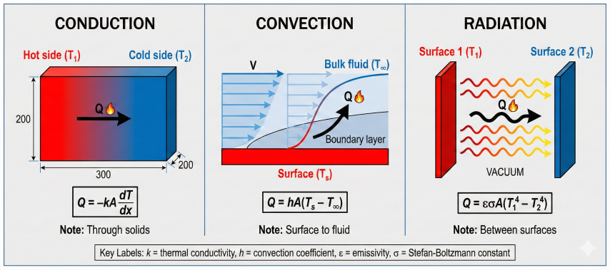
Conduction
Solid materials
Heat transfer through pipe walls, vessel shells, and insulation materials.
Convection
Fluid motion
Heat transfer between fluid and solid surface (forced or natural convection).
Radiation
Electromagnetic waves
Heat transfer via infrared radiation (significant at high temperatures).
Combined modes
Simultaneous transfer
Most real systems involve multiple modes (overall heat transfer coefficient).
Fundamental Heat Transfer Equation
Three heat transfer modes: Conduction through solids (Q=-kA·dT/dx), convection to fluids (Q=hA·ΔT), radiation between surfaces (Q=εσA·ΔT⁴).
First Law of Thermodynamics (Energy Balance):
Q = ṁ × Cp × ΔT
Where:
Q = Heat transfer rate (Btu/hr or W)
ṁ = Mass flow rate (lb/hr or kg/s)
Cp = Specific heat capacity (Btu/lb·°F or J/kg·K)
ΔT = Temperature change (°F or K)
For constant pressure process:
Q = ṁ × Cp × (T_out - T_in)
Example:
Heat natural gas from 60°F to 120°F at 1000 lb/hr:
Cp ≈ 0.5 Btu/lb·°F (at avg conditions)
Q = 1000 × 0.5 × (120 - 60) = 30,000 Btu/hr
Applications in Midstream Operations
Application
Heat Transfer Type
Typical Duty
Gas-gas heat exchanger (feed preheating)
Convection (both sides)
0.5-5 MMBtu/hr
Gas-liquid heat exchanger (reboiler)
Convection + boiling
1-20 MMBtu/hr
Pipeline heat loss (buried)
Conduction to soil
10-50 Btu/hr·ft
Insulated vessel heat loss
Conduction + convection + radiation
100-1000 Btu/hr
Fired heater (process heating)
Radiation + convection
10-100 MMBtu/hr
Overall heat transfer coefficient (U): In most equipment, heat must pass through multiple resistances (inside fluid film, pipe wall, outside fluid film, fouling layers). The overall coefficient U combines all resistances into a single value for design calculations. Typical U values: gas-gas 5-50, liquid-liquid 50-300, condensing vapor 100-500 Btu/hr·ft²·°F.
2. Heat Transfer Mechanisms
Conduction (Fourier's Law)
One-Dimensional Steady-State Conduction:
Q = -k × A × (dT/dx)
For constant area and thermal conductivity:
Q = k × A × (T₁ - T₂) / L
Where:
Q = Heat transfer rate (Btu/hr or W)
k = Thermal conductivity (Btu/hr·ft·°F or W/m·K)
A = Cross-sectional area perpendicular to heat flow (ft² or m²)
T₁, T₂ = Temperatures at locations 1 and 2 (°F or K)
L = Distance between locations (ft or m)
Thermal resistance:
R_cond = L / (k × A) (°F·hr/Btu or K/W)
Example - Pipe wall conduction:
For cylindrical coordinates (radial conduction through pipe wall):
Q = 2π × k × L × (T_i - T_o) / ln(r_o / r_i)
Where:
L = Pipe length (ft)
r_i, r_o = Inner and outer radii (ft)
T_i, T_o = Inner and outer surface temperatures (°F)
Thermal Conductivity Values
Material
k (Btu/hr·ft·°F)
k (W/m·K)
Application
Carbon steel (pipe)
25-30
43-52
Pipeline, pressure vessels
Stainless steel 316
8-10
14-17
Process piping, heat exchanger tubes
Fiberglass insulation
0.02-0.025
0.035-0.043
Pipe/vessel insulation
Mineral wool
0.022-0.028
0.038-0.048
High-temperature insulation
Polyurethane foam
0.012-0.016
0.021-0.028
Cryogenic insulation (LNG)
Concrete (buried pipe)
0.4-0.8
0.7-1.4
Pipe coatings, foundations
Soil (moist)
0.5-1.5
0.9-2.6
Buried pipeline heat transfer
Convection (Newton's Law of Cooling)
Convective Heat Transfer:
Q = h × A × (T_s - T_∞)
Where:
Q = Heat transfer rate (Btu/hr or W)
h = Convective heat transfer coefficient (Btu/hr·ft²·°F or W/m²·K)
A = Surface area (ft² or m²)
T_s = Surface temperature (°F or K)
T_∞ = Bulk fluid temperature (°F or K)
Thermal resistance:
R_conv = 1 / (h × A) (°F·hr/Btu or K/W)
Convection types:
1. Forced convection: External force (pump, fan) drives fluid motion
2. Natural convection: Buoyancy-driven flow from density gradients
3. Boiling/condensation: Phase change enhances heat transfer
Convection Coefficient Correlations
Convection coefficients depend on fluid properties, flow regime, and geometry. Common correlations:
Dittus-Boelter Equation (Turbulent Flow in Pipes):
Nu = 0.023 × Re^0.8 × Pr^n
Where:
Nu = Nusselt number = h × D / k
Re = Reynolds number = ρ × V × D / μ
Pr = Prandtl number = Cp × μ / k
n = 0.4 for heating, 0.3 for cooling
Valid for:
- Re > 10,000 (turbulent)
- 0.7 < Pr < 160
- L/D > 10 (fully developed)
Example:
Natural gas in 4" pipe, Re = 50,000, Pr = 0.75:
Nu = 0.023 × 50,000^0.8 × 0.75^0.4 = 118
If k = 0.02 Btu/hr·ft·°F, D = 0.333 ft:
h = Nu × k / D = 118 × 0.02 / 0.333 = 7.1 Btu/hr·ft²·°F
Typical Convection Coefficients
Fluid/Condition
h (Btu/hr·ft²·°F)
h (W/m²·K)
Natural gas (forced convection)
5-25
28-142
Water (forced convection)
300-3,000
1,700-17,000
Oil/liquid hydrocarbons
50-500
284-2,840
Condensing steam
1,000-5,000
5,680-28,400
Boiling water
500-5,000
2,840-28,400
Air (natural convection)
1-5
6-28
Air (forced, 10 mph wind)
5-10
28-57
Radiation (Stefan-Boltzmann Law)
Thermal Radiation:
Q = ε × σ × A × (T₁⁴ - T₂⁴)
Where:
Q = Radiant heat transfer rate (Btu/hr or W)
ε = Emissivity (0-1, dimensionless)
σ = Stefan-Boltzmann constant
= 0.1714×10⁻⁸ Btu/hr·ft²·°R⁴
= 5.67×10⁻⁸ W/m²·K⁴
A = Surface area (ft² or m²)
T₁, T₂ = Absolute temperatures (°R = °F+459.67, or K)
For small temperature differences, linearized form:
Q ≈ h_r × A × (T₁ - T₂)
Where h_r = ε × σ × (T₁² + T₂²) × (T₁ + T₂)
Radiation typically important when:
- High temperatures (> 500°F)
- Low convection coefficients (gas/air)
- View factor close to 1 (large surfaces facing each other)
Emissivity Values
Surface
Emissivity (ε)
Notes
Polished aluminum
0.05-0.10
Reflective, low radiation
Oxidized steel
0.80-0.90
Typical piping/vessels
Painted surface (any color)
0.85-0.95
Paint increases emissivity
Black body (theoretical)
1.00
Perfect emitter/absorber
Insulation jacket (aluminum)
0.10-0.20
Reduces radiant heat loss
Combined heat transfer: In most practical cases, all three modes occur simultaneously. For example, heat loss from an insulated pipe involves: conduction through pipe wall and insulation, convection to ambient air, and radiation to surroundings. Use overall heat transfer coefficient U to combine all resistances in series.
3. LMTD Method (Log Mean Temperature Difference)
The LMTD method is the standard approach for rating (checking performance of) existing heat exchangers or designing new ones when inlet/outlet temperatures are known.
Overall Heat Transfer Equation
Basic Heat Exchanger Equation:
Q = U × A × LMTD × F_t
Where:
Q = Heat duty (Btu/hr or W)
U = Overall heat transfer coefficient (Btu/hr·ft²·°F or W/m²·K)
A = Heat transfer area (ft² or m²)
LMTD = Log mean temperature difference (°F or K)
F_t = Temperature correction factor for exchanger configuration
This equation applies to all heat exchanger types (shell-and-tube,
plate, air-cooled, etc.).
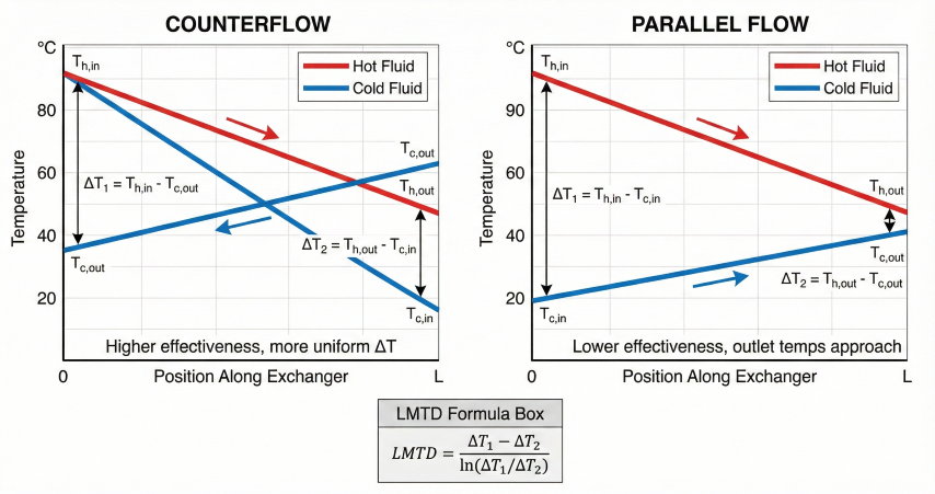
LMTD Calculation
Temperature profiles: Counterflow maintains higher average ΔT for better effectiveness; parallel flow has converging outlet temperatures.
Problem:
Heat natural gas from 60°F to 100°F using hot oil cooling from
200°F to 150°F in a countercurrent heat exchanger.
Gas flow: 10,000 lb/hr (Cp = 0.52 Btu/lb·°F)
Calculate LMTD and required area if U = 15 Btu/hr·ft²·°F.
Solution:
Step 1: Calculate duty from gas side
Q = ṁ × Cp × ΔT
Q = 10,000 × 0.52 × (100 - 60) = 208,000 Btu/hr
Step 2: Verify from oil side (energy balance)
Q = ṁ_oil × Cp_oil × (200 - 150)
208,000 = ṁ_oil × 0.5 × 50
ṁ_oil = 8,320 lb/hr ✓
Step 3: Calculate LMTD (counterflow)
ΔT₁ = T_h,in - T_c,out = 200 - 100 = 100°F
ΔT₂ = T_h,out - T_c,in = 150 - 60 = 90°F
LMTD = (100 - 90) / ln(100/90)
LMTD = 10 / ln(1.111)
LMTD = 10 / 0.1054 = 94.9°F
Step 4: Calculate required area (assume F_t = 1.0 for true counterflow)
Q = U × A × LMTD × F_t
208,000 = 15 × A × 94.9 × 1.0
A = 208,000 / (15 × 94.9) = 146 ft²
Result: Require ~150 ft² heat transfer area.
For shell-and-tube with 3/4" OD tubes, 10 ft long:
Area per tube = π × (0.75/12) × 10 = 1.96 ft²
Number of tubes = 150 / 1.96 = 77 tubes
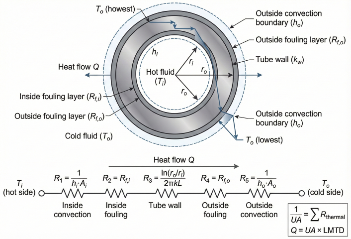
Overall Heat Transfer Coefficient (U)
Thermal resistance network: Heat passes through five resistances in series; overall U determined by sum of individual resistances.
Resistance Network (Series Resistances):
1/U = 1/h_i + (r_o ln(r_o/r_i))/k_w + R_f,i × (A_o/A_i) + R_f,o + 1/h_o
Where:
h_i = Inside fluid film coefficient (Btu/hr·ft²·°F)
h_o = Outside fluid film coefficient
k_w = Tube wall thermal conductivity
r_i, r_o = Inner and outer tube radii
R_f,i, R_f,o = Fouling resistances (inside and outside)
A_i, A_o = Inside and outside tube areas
For thin-walled tubes, wall resistance negligible:
1/U ≈ 1/h_i + R_f,i + R_f,o + 1/h_o
Note: U based on outside area A_o is common convention.
Fouling factors (from TEMA standards):
- Clean gas: R_f = 0.001 hr·ft²·°F/Btu
- Clean water: R_f = 0.001
- Treated cooling water: R_f = 0.002
- River water: R_f = 0.003-0.005
- Light hydrocarbons: R_f = 0.001-0.002
- Heavy oils: R_f = 0.003-0.005
Typical Overall U Values
Fluid Combination
U (Btu/hr·ft²·°F)
U (W/m²·K)
Controlling Resistance
Gas to gas
5-50
28-284
Both film coefficients low
Gas to liquid
10-80
57-454
Gas-side film coefficient
Liquid to liquid (light oils)
50-200
284-1,135
Fouling and film coefficients
Liquid to liquid (water/water)
200-500
1,135-2,840
Mainly fouling
Condensing vapor to liquid
100-500
568-2,840
Liquid-side film + fouling
Boiling liquid (reboiler)
100-300
568-1,703
Heating medium-side film
Temperature Correction Factor (F_t)
For shell-and-tube exchangers with multiple tube passes, flow is not true counterflow. Correction factor F_t accounts for this:
F_t Calculation:
F_t depends on two dimensionless parameters:
P = (t₂ - t₁) / (T₁ - t₁) (temperature effectiveness)
R = (T₁ - T₂) / (t₂ - t₁) (capacity ratio)
Where:
T₁, T₂ = Shell-side inlet and outlet temperatures
t₁, t₂ = Tube-side inlet and outlet temperatures
F_t is read from charts (TEMA, Kern) based on P, R, and number of shell/tube passes.
Typical values:
- True counterflow (1 shell pass, many tube passes): F_t = 1.0
- 1 shell pass, 2 tube passes: F_t = 0.85-0.95
- 1 shell pass, 4+ tube passes: F_t = 0.75-0.90
- 2 shell passes: F_t = 0.90-0.98
Design guideline: F_t should be > 0.75 for economical design.
If F_t < 0.75, consider adding shell passes or switching to true counterflow.
4. Effectiveness-NTU Method
The effectiveness-NTU (Number of Transfer Units) method is preferred when outlet temperatures are unknown, common in preliminary design and performance rating with unknown fouling.
Effectiveness Definition:
ε = Q_actual / Q_max
Where:
Q_actual = Actual heat transfer rate
Q_max = Maximum possible heat transfer rate
Maximum heat transfer occurs when the fluid with minimum heat capacity
rate experiences the largest possible temperature change:
Q_max = C_min × (T_h,in - T_c,in)
Where:
C_min = min(C_h, C_c)
C_h = ṁ_h × Cp_h (hot fluid heat capacity rate, Btu/hr·°F)
C_c = ṁ_c × Cp_c (cold fluid heat capacity rate)
Heat capacity ratio:
C_r = C_min / C_max
Note: 0 ≤ C_r ≤ 1
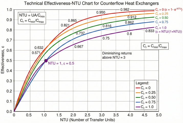
Number of Transfer Units (NTU)
NTU Definition:
NTU = U × A / C_min
Where:
U = Overall heat transfer coefficient (Btu/hr·ft²·°F)
A = Heat transfer area (ft²)
C_min = Minimum heat capacity rate (Btu/hr·°F)
Physical meaning: NTU represents the "thermal size" of the exchanger.
- Large NTU (> 5): Approaches temperature equilibrium
- Small NTU (< 1): Limited heat transfer
Relationship to effectiveness:
ε = f(NTU, C_r, flow configuration)
The function f depends on exchanger type (counterflow, parallel flow,
cross-flow, shell-and-tube, etc.).
Effectiveness Relations for Common Configurations
Counterflow:
For C_r < 1:
ε = [1 - exp(-NTU × (1 - C_r))] / [1 - C_r × exp(-NTU × (1 - C_r))]
For C_r = 1 (balanced flow):
ε = NTU / (1 + NTU)
Parallel Flow (Cocurrent):
ε = [1 - exp(-NTU × (1 + C_r))] / (1 + C_r)
Condenser or Evaporator (C_r = 0, one fluid phase change):
ε = 1 - exp(-NTU)
Note: This applies when one fluid's temperature is constant (condensing
steam, boiling liquid in pool). NTU = UA / C_min where C_min is the
single-phase fluid.
Cross-Flow (both fluids unmixed):
ε = 1 - exp[(NTU^0.22 / C_r) × (exp(-C_r × NTU^0.78) - 1)]
Note: More complex; use charts or approximations for practical calculations.
Method selection: Use LMTD when all four temperatures are known or specified (rating existing exchangers, verifying vendor proposals). Use NTU when designing new exchangers with unknown outlet temperatures (sizing calculations, sensitivity studies). Both methods give identical results when applied correctly.
5. Applications & Design Considerations
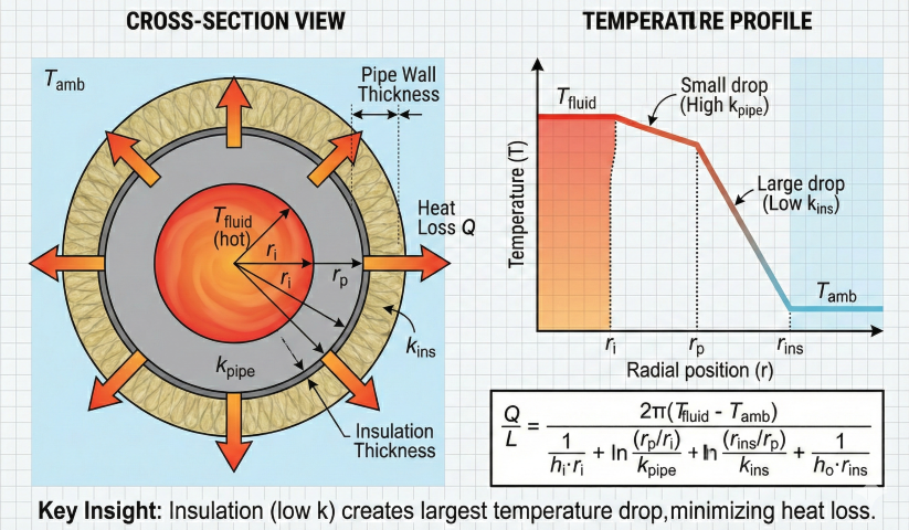
Pipeline Heat Loss Calculation
Insulated pipe heat loss: Low thermal conductivity of insulation creates largest temperature drop, minimizing heat loss to surroundings.
Minimum Temperature Approach:
ΔT_min = Minimum temperature difference between hot and cold streams
at any point in exchanger
For counterflow:
ΔT_min = min(T_h,out - T_c,in, T_h,in - T_c,out)
Typical minimum approaches:
- Gas-gas: 20-50°F (large ΔT needed due to low U)
- Liquid-liquid: 10-20°F
- Condensing/boiling: 10-30°F (depends on process)
- Refrigeration: 5-10°F (tight approach for efficiency)
Small ΔT_min → large exchanger (expensive)
Large ΔT_min → small exchanger but less heat recovery
Pinch point: Location of minimum ΔT in process heat exchanger network.
Determines maximum heat recovery in multi-exchanger systems.
Heat Exchanger Selection Guide
Type
Best Application
Advantages
Limitations
Shell & tube
General purpose, high P/T
Robust, repairable, TEMA standardized
Large footprint, expensive
Plate & frame
Liquid-liquid, moderate P/T
Compact, high U, easy cleaning
Gasket limited (< 400°F, < 300 psi)
Plate-fin (brazed)
Gas service, cryogenic
Very compact, high effectiveness
Not repairable, fouling-sensitive
Air-cooled (fin-fan)
Gas/liquid cooling, no water available
No water consumption, low maintenance
Large, ambient-dependent, high power (fans)
Double-pipe
Small duty (< 1 MMBtu/hr)
Simple, true counterflow, low cost
Limited area, high pressure drop
Fouling factor importance: Fouling reduces U by 20-50% over operating life. Always include TEMA-recommended fouling factors in design calculations. Clean exchanger performance will exceed design, but fouled performance must still meet process requirements. Schedule cleaning when measured U drops below 80% of clean design value.
The three modes of heat transfer are conduction (through solid materials), convection (between a surface and moving fluid), and radiation (electromagnetic energy transfer).
What is the overall heat transfer coefficient?+
The overall heat transfer coefficient (U) combines all thermal resistances including convection on both sides, tube wall conduction, and fouling into a single value for heat exchanger sizing.
What design methods are used for heat exchanger thermal analysis?+
The two primary methods are the LMTD (Log Mean Temperature Difference) method and the effectiveness-NTU method, each suited to different design scenarios.