1. Layout Principles
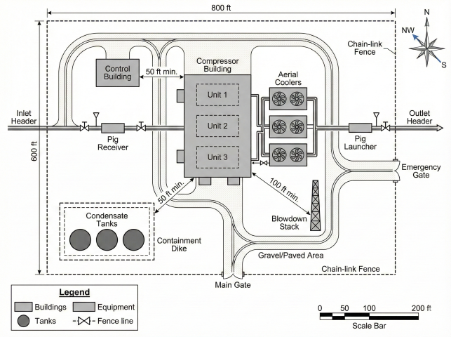
The layout of a compressor station depends on location, proximity to homes and businesses, vegetation, predominant wind direction, and land contour. Equipment placement must minimize impact on the local environment while providing safe and efficient operations.
Primary Design Objectives
- Fire protection: Adequate access for fire fighting equipment and personnel
- Operations: Efficient access for routine operations and monitoring
- Maintenance: Space for equipment removal, laydown, and crane access
- Personnel safety: Protection from hazards and clear evacuation routes
- Equipment protection: Separation from ignition sources and hazardous areas
- Adjacent properties: Prevention of danger or nuisance to neighbors
General Layout Considerations
- Future expansion: The compressor building shall be located to allow addition of future compression and/or gas cooling
- Wind direction: Vents shall be placed so hydrocarbon vapors do not pass over potential ignition sources
- Site security: Local conditions may require increased or decreased spacing from property line
- Adjacent development: Consider current and future proximity of homes, businesses, and public areas
- Terrain: Use natural features for noise screening and drainage
Access Requirements
The facility layout must provide:
- Access to individual equipment for maintenance while adjacent facilities remain in operation
- Sufficient exit doors from compressor building to provide escape from any point
- Emergency vehicle access around the perimeter of major equipment areas
- Crane access for equipment removal and replacement
2. Equipment Spacing Requirements
Minimum spacing requirements provide adequate safety margins for operations, maintenance, fire protection, and emergency response. These distances are based on industry practice and regulatory requirements.
Building Separation Distances
| From | To | Minimum Distance |
|---|---|---|
| Compressor building | Control building | 50 ft |
| Compressor building | Shop/warehouse | 50 ft |
| Compressor building | Boiler building | 50 ft |
| Compressor building | General office building | 50 ft |
Note: Control building should preferably be located on the free air and exhaust side of the compressor building.
Vent and Blowdown Distances
| System | Minimum Distance from Compressor Building |
|---|---|
| Blowdown vent header discharge | 100 ft |
| Compressor unit piping vent system | 100 ft |
| Cranking gas vent header | 100 ft |
Storage Tank Distances
| Equipment | Minimum Distance | From |
|---|---|---|
| Pipeline condensate storage tanks | 50 ft | Any building |
| Pipeline condensate storage tanks | 50 ft | Operating equipment |
| Pipeline condensate storage tanks | 50 ft | Source of ignition |
Property Line Considerations
Distance from facility to property line depends on:
- Type of facility nearest the boundary
- Nature of adjacent property (industrial vs. residential)
- Local noise ordinances and zoning requirements
- Potential for light, odor, and noise impacts
In residential areas, additional space for screening may be required to mitigate light, noise, and odor impacts.
3. Emergency Shutdown (ESD) Requirements
Per 49 CFR 192, each compressor station (except unattended field stations of 1,000 HP or less) must have an emergency shutdown system meeting specific requirements.
ESD System Capabilities
The emergency shutdown system must:
- Block gas out of the station and blow down the station piping
- Discharge gas from blowdown piping at a location where gas will not create a hazard
- Provide means for shutdown of gas compressing equipment, gas fires, and electrical facilities in the vicinity of gas headers
ESD Actuation Points
| Requirement | Specification |
|---|---|
| Number of actuation locations | Minimum 2 locations |
| Location requirement | Outside the gas area of the station |
| Placement (fenced station) | Near exit gates |
| Placement (unfenced station) | Near emergency exits |
| Maximum distance from station | 500 ft from station limits |
| Distance from compressor building | Minimum 25 ft |
Electrical Circuits Exceptions
The following electrical circuits may remain energized during ESD:
- Emergency lighting: Circuits that supply lighting required to assist personnel in evacuating the compressor building and gas header area
- Equipment protection: Circuits needed to protect equipment from damage
Fuel Gas Shutdown
The compressor building fuel gas shutdown system shall have block and bleed valves located outside of the compressor building.
Distribution System Supply: If a compressor station supplies gas directly to a distribution system with no other adequate source available, the ESD system must be designed so it will not function at the wrong time and cause an unintended outage.
Automatic ESD Triggers (Offshore/Inland Navigable Waters)
For platforms located offshore or in inland navigable waters, the ESD must actuate automatically for:
Unattended Compressor Stations:
- Gas pressure reaches MAOP + 15%
- Uncontrolled fire occurs on platform
Compressor Stations in Buildings:
- Uncontrolled fire occurs in building
- Gas concentration reaches 50% or more of LEL in a building with ignition source
4. Noise Considerations
FERC requires noise estimates for any new or modified facility. Noise is often the controlling factor in equipment placement and orientation.
FERC Noise Limits
| Parameter | Limit | Description |
|---|---|---|
| Ldn | 55 dBA | Day-night equivalent sound level at NSA |
| Leq (equivalent) | 48.6 dBA | Continuous equivalent for 24-hour operation |
Note: The 55 dBA Ldn limit applies to station contribution only at noise-sensitive areas (NSAs). Environmental noise from traffic, aircraft, etc. is excluded.
Noise-Sensitive Areas (NSAs)
NSAs include:
- Residences
- Schools
- Hospitals
- Churches
- Playgrounds
- Farms
- Camping facilities
Layout Strategies for Noise Control
- Maximize distance from noise-generating equipment to NSAs
- Consider prevailing wind direction (sound travels farther downwind)
- Use terrain features as natural noise barriers
- Position buildings or trees as noise screens
- Orient equipment exhaust away from NSAs
Noise Abatement Options
| Source | Abatement Method |
|---|---|
| Turbine inlet/exhaust | Additional silencing |
| Gas engine exhaust | Hospital grade silencers |
| High-velocity piping/valves | Sound insulation or burial |
| Aerial coolers | Reduced fan speeds, acoustical hoods |
| Compressor building | Acoustical wall/roof insulation |
Noise Survey Requirements
- New facilities: Baseline survey of environmental noise before construction
- Modified facilities: Survey with existing facilities at full load (avoid unusual/extraneous noise)
- Modeling: Expected noise from additions modeled over baseline
5. Air Emissions
Air emissions must be evaluated early in planning for any horsepower addition or modification. Emission considerations can significantly impact driver selection and project costs.
Emission Evaluation Checklist
- Existing emissions and permit conditions
- Attainment vs. non-attainment area status
- NOx, CO, and unburned hydrocarbon levels
- Anticipated emissions from proposed addition
- Control requirements for acceptable emission levels
- Existing horsepower that can be shut down/removed
- Project timing vs. permit acquisition time
Major Source Thresholds (MST)
| Area Status | MST | Notes |
|---|---|---|
| Attainment | 250 T/yr | Any pollutant |
| Non-attainment (marginal) | 100 T/yr | Varies by pollutant |
| Non-attainment (severe) | 25 T/yr | Most restrictive |
Title V Permit Triggers
| Pollutant | Attainment Area | Non-attainment Area |
|---|---|---|
| NOx | 100 T/yr | 50 or 25 T/yr |
| CO | 100 T/yr | 50 or 25 T/yr |
Typical Driver Emission Levels
| Driver Type | NOx | CO |
|---|---|---|
| Gas turbine (dry low NOx) | 25 ppmvd @ 15% O2 | Varies |
| Clean-burn gas engine | 0.7 g/bhp-hr | 1.9 g/bhp-hr |
| Electric motor | Zero | Zero |
New Source Review: If PTE exceeds MST or Significant Emission Rate (SER), the facility is subject to New Source Review (NSR) and BACT/LAER review. Early involvement of environmental specialists is critical.
6. Driver Selection Impact on Layout
The choice of prime mover/compressor package affects facility layout, spacing requirements, and infrastructure needs.
Common Driver/Compressor Combinations
| Driver | Compressor | Layout Considerations |
|---|---|---|
| Electric motor | Reciprocating | Substation space, cooling requirements |
| Electric motor | Centrifugal | Higher flow, smaller footprint |
| Gas engine | Reciprocating | Exhaust stack, fuel gas system, noise |
| Gas turbine | Centrifugal | Inlet air, exhaust, larger setbacks |
Selection Factors
- Pipeline conditions: Suction/discharge pressures, gas volume, flow variability
- Operating philosophy: Base load vs. swing/peaking service
- Existing equipment: Compatibility with maintenance, spare parts
- Control requirements: Manned vs. remote operation
- Operating costs: Fuel/electricity costs, efficiency
- Installation cost: Package cost plus utilities, buildings, site work
- Delivery time: Compressor package typically longest lead item
- Station location: Neighborhood, environmental constraints, space
- Air emissions: Permit requirements, attainment status
- Noise: Local ordinances, NSA proximity
- Project life: Short life may not justify higher capital cost
General Application Guidelines
- Centrifugal: Preferred for high flow or low compression ratios
- Reciprocating: Preferred for low flow or higher compression ratios
- Electric: Zero site emissions, lower noise, higher efficiency
- Gas-fired: No electrical infrastructure, fuel available on-site
7. Station-to-Station Spacing on Pipelines
Beyond within-station layout, a fundamental design question is how far apart compressor stations should be located along a transmission pipeline. Station spacing is driven by hydraulics, not equipment clearances — it is measured in miles, not feet.
Typical Spacing Ranges
On natural gas transmission pipelines, compressor stations are typically spaced 50 to 200 miles apart, depending on pipeline diameter, operating pressure, flow rate, and terrain. Common ranges by application:
| Pipeline Type | Typical Station Spacing | Key Driver |
|---|---|---|
| Large-diameter interstate transmission (30–42 in) | 50–100 miles | Allowable pressure drop at high flow rates |
| Medium-diameter transmission (16–24 in) | 75–150 miles | Balance of throughput and compression cost |
| Smaller or low-flow transmission (8–16 in) | 100–200 miles | Lower frictional losses allow wider spacing |
| High-altitude or mountainous terrain | 40–80 miles | Elevation changes increase compression demand |
Factors Affecting Station Spacing
Station spacing is determined during pipeline hydraulic design and depends on several interrelated factors:
- Allowable pressure drop: Gas pressure decreases along the pipeline due to friction. When pressure drops to the minimum acceptable level (typically the MAOP of the downstream segment or the minimum delivery pressure), a compressor station is needed to boost pressure back up. Greater allowable pressure drop permits wider station spacing.
- Pipeline diameter: Larger-diameter pipelines have lower frictional pressure loss per mile, allowing stations to be spaced farther apart. Per the general flow equation (Weymouth: Q² ∝ D16/3), the friction-driven pressure drop at constant flow scales as D−16/3, so doubling the diameter reduces friction pressure loss by a factor of roughly 30–40.
- Flow rate (throughput): Higher flow rates increase frictional losses, requiring more frequent compression. A pipeline designed for 1 Bcf/d will need closer station spacing than the same diameter pipeline at 500 MMcf/d.
- Gas composition and properties: Heavier gas (higher specific gravity) or gas with higher compressibility factors may require different compression strategies and station spacing.
- MAOP and compression ratio: The maximum allowable operating pressure sets the upper limit for discharge pressure. The compression ratio (discharge/suction pressure) at each station is typically kept between 1.2 and 1.6 for centrifugal units and up to 2.0 or higher for reciprocating units.
- Terrain and elevation: Mountainous routes with significant elevation gains require more compression energy, often resulting in closer station spacing on uphill segments.
- Ambient temperature: Gas temperature affects compression efficiency and gas density. Aftercooling capacity at each station influences discharge conditions and downstream hydraulics.
Hydraulic Design Approach
Station locations are determined through steady-state hydraulic simulation of the full pipeline system. The general approach:
- Establish design throughput, receipt and delivery pressures, and gas properties
- Model the pipeline profile (diameter, wall thickness, elevation changes, pipe roughness)
- Calculate pressure drop along the route using the general flow equation (Weymouth, Panhandle A or B, or AGA equations)
- Identify locations where suction pressure falls to the minimum acceptable level — these define station locations
- Size compression at each station to achieve the required discharge pressure within allowable compression ratios
- Iterate to optimize the number and size of stations for capital and operating cost
Design Rules of Thumb
- For preliminary planning on a typical 24–36 inch transmission pipeline operating at 800–1,200 psig and flowing 500 MMcf/d to 1 Bcf/d, plan for compressor stations approximately 75 to 100 miles apart
- Each compressor station adds approximately 3,000 to 20,000 HP of installed compression, depending on throughput and compression ratio
- Total pipeline horsepower per mile of pipeline is typically 50 to 200 HP/mile for major transmission systems
- Station spacing should be validated through steady-state simulation before finalizing station locations
- Consider future expansion: initial station spacing should accommodate increased throughput by adding compression units rather than additional stations
8. Code Requirements
Applicable Regulations & Standards
| Code/Standard | Scope | Authority |
|---|---|---|
| 49 CFR Part 192 | Gas transmission/distribution pipelines | DOT/PHMSA (Federal) |
| FERC Regulations | Interstate gas transmission facilities | FERC (Federal) |
| NFPA 30 | Flammable liquids storage | Industry standard |
| NFPA 70 (NEC) | Electrical installations | Industry standard |
| API RP 500/505 | Electrical area classification | Industry standard |
| State/Local codes | Building, fire, zoning | Varies by jurisdiction |
Key Regulatory Requirements
- ESD system: Required for stations >1,000 HP per 49 CFR 192
- Noise limit: 55 dBA Ldn at NSA per FERC
- Air permits: Required based on PTE vs. thresholds
- Hazardous area classification: Per API RP 500/505
- Fire protection: Per NFPA and local requirements
Summary: Minimum Spacing Quick Reference
| Item | Minimum Distance |
|---|---|
| Control/office building from compressor building | 50 ft |
| Condensate tanks from buildings/equipment | 50 ft |
| Blowdown/vent discharge from compressor building | 100 ft |
| ESD actuation from compressor building | 25 ft (minimum) |
| ESD actuation from station limits | 500 ft (maximum) |
References
- 49 CFR Part 192 – Transportation of Natural Gas by Pipeline (DOT/PHMSA)
- 18 CFR Part 380 – FERC Environmental Review Regulations
- API RP 500 – Classification of Locations for Electrical Installations
- API RP 505 – Classification of Locations for Electrical Installations (Zone System)
- NFPA 30 – Flammable and Combustible Liquids Code
- NFPA 70 – National Electrical Code
- ASME B31.8 – Gas Transmission and Distribution Piping Systems
Ready to use the calculator?
→ ESD System Design Fundamentals