1. Introduction
The plant protection system provides tiered responses to successive levels of hazard. The most significant hazards (fire) trigger a full plant Emergency Shutdown (ESD). Less significant hazards may limit operation to a single building or unit without full station isolation.
Regulatory Framework
- 49 CFR Part 192: Transportation of Natural Gas by Pipeline - Minimum Federal Safety Standards
- NEC (NFPA 70): National Electrical Code requirements for installations
- State/Local regulations: Municipal, state, and federal regulations as applicable
Applicability
ESD functions shall be implemented for all compressor stations of 1,000 installed horsepower or more. Unattended field compressor stations of 1,000 HP or less are exempt from some requirements.
Protection System Levels
| Level | Response | Scope |
|---|---|---|
| Plant ESD | Full isolation and blowdown | Entire station |
| Fuel Gas Shutdown (FGS) | Block/vent fuel, unit stops | Single building |
| Unit Shutdown | Individual unit stop | Single compressor |
| Alarm Only | Annunciation, time-limited | Monitoring point |
2. Plant ESD System
The Plant ESD System isolates the compressor station from the pipeline and vents the station yard high-pressure piping to atmosphere. It is the response dictated for the most significant hazard expected (fire).
ESD System Functions
- Block gas out of the station (close side valves)
- Blow down station piping to atmosphere
- Shut down gas compressing equipment
- De-energize electrical facilities in gas header area
- Discharge gas at a location where it will not create a hazard
Pneumatic Control System
The ESD operates by directing high-pressure gas from a secure source into a pneumatic control line. The control line is pressurized to activate the ESD.
| Component | Requirement |
|---|---|
| Volume storage vessel | Fed from highest pipeline pressure available |
| Control gas line size | 2" nominal minimum |
| Valve actuation time | All valves within 10 seconds |
| Valve operators | Direct acting, no spring return required |
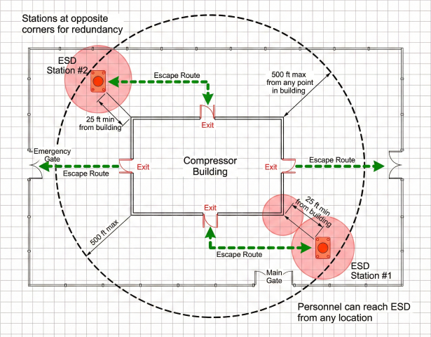
Manual Control Stations
At least two manually operated pneumatic control stands shall exist to initiate the system by pressurizing the Control Gas line:
- One located in a safe area accessible during fire near compressor building
- Outside the gas area of the station
- Near exit gates (fenced station) or emergency exits (unfenced)
- Maximum 500 ft from station limits
- Minimum 25 ft from compressor building
Valve Operations During ESD
| Valve Type | Action on ESD | Actuation |
|---|---|---|
| Side valves (inlet/outlet) | Close | Direct from control gas line |
| Blow-off valves | Open (vent to atmosphere) | Direct from control gas line |
| Bypass valves | Position as required | May be electric (non-critical) |
Electric ESD Initiation
Two design principles are acceptable for electrically initiated ESD:
Option 1: Master ESD Circuit (Fail-Safe)
- Normally energized solenoid control valve
- Breaking the circuit activates ESD
- Provides true fail-safe operation
- Any wire break, power loss, or button press triggers ESD
Option 2: Supervised Circuit
- Normally de-energized solenoid
- Energizing the circuit activates ESD
- Circuit continuity is monitored
- Failures are annunciated without triggering ESD
Master ESD Circuit: When required, the Master ESD Circuit shall be routed through dedicated conduit. All conduit and fittings shall be dedicated to the circuit and shall not share any other circuits.
3. Fuel Gas Shutdown (FGS)
The Fuel Gas Shutdown is a response to a lesser hazard, limiting the response to a single building without requiring isolation and blowdown of the entire station yard piping.
FGS Components
| Component | Function |
|---|---|
| Fuel block valve | Isolates fuel gas supply to building |
| Fuel vent valve | Vents fuel piping to atmosphere |
| Unit controls | Forces suction/discharge valves closed |
| Case vent | Vents compressor cases |
| Electrical disconnect | De-energizes non-essential circuits |
FGS Operation
- Fuel blocked and vented by pair of flow control valves
- Solenoid control valve operates pilot to position block/vent valves
- Pneumatic connection to ESD control gas line preferred
- ESD activation also causes FGS
- Block/vent valves shall not reposition when ESD control gas is de-pressurized
Unit Shutdown Methods
| Stop Type | Description | Application |
|---|---|---|
| Emergency Stop | Immediate shutdown, case vented | Safety-critical situations |
| Fast Stop | Rapid shutdown with case venting | Lesser hazards (with vent provision) |
| Normal Stop | Controlled shutdown sequence | Routine operations |
FGS vs. ESD Comparison
| Feature | ESD | FGS |
|---|---|---|
| Scope | Entire station | Single building |
| Pipeline isolation | Yes | No |
| Yard piping blowdown | Yes | No |
| Fuel gas blocked | Yes | Yes (building only) |
| Units affected | All | Building units only |
4. Detection Systems
A standard set of instrumentation shall be provided for compressor buildings to protect personnel and equipment. For unattended facilities, this includes flame detection, fire detection, and hazardous gas detection.
Required Detection Types
| Detection Type | Technology | Purpose |
|---|---|---|
| Flame Detection | UV/IR optical | Detect oil fires at compressor base |
| Fire Detection | High heat detectors | Detect hot gases near roof |
| Gas Detection | IR point or open path | Detect hydrocarbon releases |
Flame Detection
- UV/IR combination detectors for reliability
- Coverage of all locations around compressor engine base
- Primary purpose: detect oil fires
- Sufficient detectors to sense fire at any location
High Heat Detectors
- Installed near roof to detect hot gas accumulation
- Additional detectors in pits and basements with restricted airflow
- Rate-of-rise or fixed temperature types
Hazardous Gas Detectors
Required in all compressor buildings:
| Detector Type | Application | Conditions |
|---|---|---|
| Open path IR | Large open areas | Building arrangement allows effective use |
| Point IR | Localized monitoring | Temperature maintained within limits |
| Catalytic bead | General purpose | Clean atmosphere required |
Detection Response Matrix
| Detection | Level 1 Response | Level 2 Response |
|---|---|---|
| Flame detected | FGS, alarm | ESD (confirmed fire) |
| High heat | Alarm, ventilation | FGS (sustained) |
| Gas 20% LEL | Alarm, ventilation | — |
| Gas 50% LEL | FGS, unit stops | ESD (automatic for offshore) |
5. Control Logic
A control system shall monitor instruments and provide control actions as needed. It shall include event recorder, annunciator, and operator interface functions.
Logic Implementation Options
- Hardwired relay-based controls
- Programmable Logic Controllers (PLCs)
- Dedicated safety processors
- Contact/button strings (simple systems)
Standard Functions Matrix
All new compressor buildings shall implement the standard protection matrix:
| Function | Type | Notes |
|---|---|---|
| High Heat Detection | Required | With fault detection |
| Ventilation Control | Required | Start/stop capability |
| Electrically Initiated ESD | Required | With fault monitoring |
| Electrically Initiated FGS | Required | With fault monitoring |
| Manually Initiated ESD | Required | With fault monitoring |
| Manually Initiated FGS | Optional | With fault monitoring |
| Shunt Trip - Lights | Required | Non-essential circuits |
| Unit Emergency Stop | Required | Hard wired |
| Unit Fast Stop w/ Vent | Required | Hard wired |
| Fire Horn | Required | Enabled when attended |
| Blue Beacon | Optional | Visual alarm |
Bypass and Testing
- Functions may be bypassed for maintenance with permanently installed switches
- All bypassed functions shall be annunciated
- Bypasses shall be automatically recorded by event recorder
- ESD and FGS test functions required
Monitoring Display Requirements
Protection system shall include dedicated monitoring display in a "safe" area:
- Event logs and operator interface
- At least two displays if merged with automation system
- One display in designated safe area
- Isolated communications circuit for safe area display
- Battery backup and standby generator power
6. Power Supply
A dedicated power supply shall be provided for the protection system with battery backup to ensure operation during power outages.
Power Supply Requirements
| Parameter | Requirement |
|---|---|
| Battery backup (no generator) | Minimum 2 hours |
| Battery backup (with generator) | Minimum 20 minutes |
| Master ESD circuit power | Dedicated feed, maximum reliability |
Acceptable Power Supply Types
Type 1: DC Battery Bank
- Large bank of DC batteries
- Redundant DC chargers
- Optional inverter for 120 VAC loads
Type 2: Commercial AC UPS
- Commercial grade AC UPS
- External bypass switch for rapid replacement
- External distribution breakers
Type 3: Distributed Small Supplies
- Multiple small DC supplies and AC inverters
- Individual power to selected loads
- Sized for load transfer after single supply failure
- Redundancy through cross-connection capability
Conduit and Wiring
When Master ESD Circuit is required:
- Route through dedicated conduit
- All conduit and fittings dedicated to ESD circuit
- No sharing with non-protection system circuits
- Underground routing preferred
- If through shared pillboxes: isolate with liquid tight (red color-coded)
Underground Routing: When routed underground, care shall be taken in placement to minimize the effect of adjacent activity. Dedicated underground routing is preferred.
7. Code Requirements
Applicable Codes & Standards
| Code/Standard | Scope |
|---|---|
| 49 CFR Part 192 | Gas transmission pipeline safety standards |
| NFPA 70 (NEC) | Electrical installations |
| API RP 14C | Analysis, design of safety systems (offshore) |
| IEC 61511 | Safety instrumented systems |
| NFPA 72 | Fire alarm and signaling code |
49 CFR 192 ESD Requirements Summary
- Required for stations >1,000 HP (except unattended field stations)
- Must block gas and blow down station piping
- Must discharge gas at safe location
- Must shut down compressors, gas fires, and electrical (except emergency lighting and equipment protection circuits)
- Operable from at least 2 locations outside gas area
- Locations near exit gates/exits, within 500 ft of station
Automatic ESD Triggers (Offshore/Inland Waters)
| Condition | Station Type | Action |
|---|---|---|
| Pressure = MAOP + 15% | Unattended | Automatic ESD |
| Uncontrolled fire on platform | Unattended | Automatic ESD |
| Uncontrolled fire in building | In building | Automatic ESD |
| Gas ≥ 50% LEL with ignition source | In building | Automatic ESD |
Electrical Exceptions During ESD
The following may remain energized during ESD:
- Emergency lighting: Required to assist personnel evacuation
- Equipment protection: Circuits needed to protect equipment from damage
References
- 49 CFR Part 192 – Transportation of Natural Gas by Pipeline (DOT/PHMSA)
- NFPA 70 – National Electrical Code
- NFPA 72 – National Fire Alarm and Signaling Code
- API RP 14C – Analysis, Design, Installation of Basic Surface Safety Systems
- Safety Instrumented Systems
- API RP 500 – Classification of Locations for Electrical Installations
Ready to use the calculator?
→ Electrical Area Classification Fundamentals