Design 2-phase and 3-phase separators using settling velocity theory, retention time requirements, L/D ratio optimization, and API 12J standards for gas-liquid separation.
Size 2-phase or 3-phase separators, scrubbers, or knockout drums.
Calculate droplet settling velocities.
Determine required retention times.
Apply pressure-corrected K-factors per GPSA.
Select separator internals and configurations.
Quick Reference
Wire mesh K
0.35
Vane pack K
0.20
Multi-cyclone K
0.50
2-phase retention
1-3 min
3-phase retention
3-10 min
Optimal L/D
2.5-4.0
1. Overview & Types
Separators are pressure vessels designed to separate gas-liquid or gas-liquid-liquid mixtures using gravity, residence time, and mechanical devices. Proper sizing ensures complete phase separation, prevents carry-over, and meets process requirements.
2-phase separator
Gas-Liquid
Separates gas from liquid (oil or water). Most common in production and transmission.
3-phase separator
Gas-Oil-Water
Separates gas, oil, and free water. Uses weir to control oil-water interface.
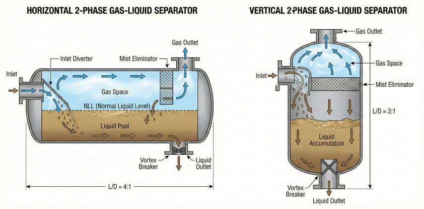
Horizontal design
High liquid loads
Better for high liquid volumes, foam control, easier maintenance access.
Vertical design
Space constrained
Smaller footprint, better for slugging, limited liquid storage, offshore platforms.
Horizontal vs vertical separator configurations showing internal components and flow paths.
Horizontal vs. Vertical Selection
Criteria
Horizontal Separator
Vertical Separator
Gas-liquid ratio
Low to moderate GOR
High GOR (> 10,000 scf/bbl)
Liquid handling
High liquid volumes
Low liquid volumes
Slugging service
Requires surge volume
Better surge handling
Foaming tendencies
Better foam control
Foam can bridge vessel
Footprint
Large footprint
Small footprint (offshore)
Maintenance
Easier internal access
Limited access
Level control
Easier liquid level control
More critical level control
Cost
Higher cost (larger vessel)
Lower cost (smaller vessel)
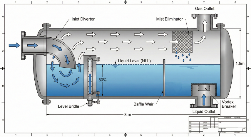
Separator Functions
Primary separation: Bulk removal of liquid from gas using momentum change at inlet
Secondary separation: Gravity settling of liquid droplets from gas phase
Liquid collection: Accumulation and storage of separated liquid phase(s)
Mist elimination: Final polishing to remove fine droplets (< 10 micron)
Interface control: Maintaining stable oil-water interface in 3-phase separators
Critical consideration: Separator sizing is governed by two independent criteria: (1) gas capacity based on droplet settling velocity, and (2) liquid capacity based on retention time. The vessel must satisfy both requirements simultaneously.
2. Settling Velocity Theory
Gas capacity sizing is based on Stokes law for droplet settling. Liquid droplets must settle out of the gas phase before reaching the outlet. The critical parameter is terminal settling velocity.
Stokes Law for Droplet Settling
Stokes Law (Laminar Flow, Re < 1):
v_t = g × d² × (ρ_L - ρ_G) / (18 × μ_G)
Where:
v_t = Terminal settling velocity (ft/s or m/s)
g = Gravitational acceleration
d = Droplet diameter (ft or m)
ρ_L = Liquid density (lb/ft³ or kg/m³)
ρ_G = Gas density (lb/ft³ or kg/m³)
μ_G = Gas dynamic viscosity (lb/ft·s or Pa·s)
For practical field units (droplet size in microns, viscosity in cP),
unit conversion factors must be applied. Our separator sizing calculator
handles these conversions automatically per GPSA methodology.
Valid for Reynolds number Re = ρ_G × v_t × d / μ_G < 1
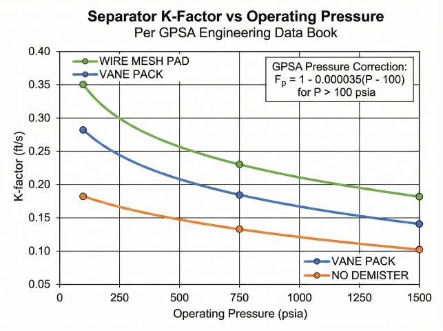
K-factor values decrease with increasing operating pressure per GPSA correlation.
Souders-Brown K-Factor Method
Industry standard for separator sizing using empirical K-factor:
Souders-Brown Equation:
v_max = K × √[(ρ_L - ρ_G) / ρ_G]
Where:
v_max = Maximum allowable gas velocity (ft/s or m/s)
K = Souders-Brown coefficient (ft/s or m/s)
K-factor selection depends on:
- Vessel orientation (horizontal vs. vertical)
- Mist eliminator type (none, wire mesh, vane pack)
- Operating pressure (K decreases at higher pressures)
K-values are empirically derived and published in GPSA
(Figure 7-9) and API 12J. Higher K-values allow higher gas velocities but
require effective mist elimination. Our calculator automatically selects
appropriate K-factors based on your configuration and applies pressure corrections.
Droplet Size Considerations
Droplet Size
Removal Method
Equipment
> 1000 micron
Momentum/Inertia
Inlet diverter, baffle
100–1000 micron
Gravity settling
Vessel residence time
10–100 micron
Coalescing
Mist eliminator
< 10 micron
Very difficult
High-efficiency coalescer, centrifugal
Design Droplet Size
Without mist eliminator: Design for 500-micron droplet (conservative)
With mesh pad eliminator: Design for 100-150 micron droplet
With vane pack: Design for 10-20 micron droplet
Critical service: Use 1000-micron droplet for ultra-conservative design
Gas Capacity Calculation - Horizontal Separator
Horizontal Separator Gas Capacity:
A_gas = Q_gas / v_max
Where:
A_gas = Effective gas cross-sectional area (ft² or m²)
Q_gas = Gas volumetric flow rate (ft³/s or m³/s at operating P/T)
v_max = Maximum gas velocity from Souders-Brown (ft/s or m/s)
For cylinder:
A_gas = (π/4) × D² × (1 - h/D)
Where:
D = Vessel inside diameter (ft or m)
h = Liquid level height (ft or m)
Typically h/D = 0.5 (half-full vessel)
Gas Capacity Calculation - Vertical Separator
Vertical Separator Gas Capacity:
D = √[4 × Q_gas / (π × v_max)]
Where:
D = Vessel inside diameter (ft or m)
Q_gas = Gas volumetric flow rate (ft³/s or m³/s)
v_max = Maximum gas velocity from Souders-Brown (ft/s or m/s)
Entire cross-section is available for gas flow (no liquid height reduction).
Practical tip: Mist eliminators increase allowable gas velocity by 50-100%, significantly reducing required separator diameter. However, they require maintenance (replacement every 2-5 years) and add pressure drop (typically 0.5-2 psi).
Knockout Drum Sizing - Critical Droplet Diameter
For knockout drums and gravity separators without mist eliminators, sizing is based on the critical droplet diameter that must be removed. The droplet size determines which flow regime applies:
Critical Droplet Diameter:
D_c = K × [μ² / (g × ρ_g × (ρ_L - ρ_g))]^(1/3)
Where:
D_c = Critical droplet diameter (ft)
μ = Gas viscosity (lb/ft·s)
g = Gravitational acceleration
ρ_g = Gas density (lb/ft³)
ρ_L = Liquid density (lb/ft³)
K = Flow regime constant (varies by Reynolds number regime)
Flow Regimes:
┌─────────────────────┬─────────────────────┐
│ Flow Regime │ Applicability │
├─────────────────────┼─────────────────────┤
│ Newton's Law │ Large droplets, │
│ │ Re > 500 │
├─────────────────────┼─────────────────────┤
│ Intermediate Law │ Medium droplets, │
│ │ 2 < Re < 500 │
├─────────────────────┼─────────────────────┤
│ Stokes Law │ Small droplets, │
│ │ Re < 2 │
└─────────────────────┴─────────────────────┘
Reynolds number check: Re = ρ_g × v_t × D_c / μ
Most gas-liquid separators operate in the Intermediate or Stokes regime.
K-values for each regime are available in standard references (Perry's, GPSA).
Gravity Settling Terminal Velocity
Terminal Velocity for Gravity Settling:
v_t = 1.73 × √[g_c × D_p × (ρ_L - ρ_G) / ρ_G]
Where:
v_t = Terminal settling velocity (ft/s)
g_c = Gravitational constant (32.174 lb-ft/lb-sec²)
D_p = Droplet diameter (ft)
ρ_L = Liquid density (lb/ft³)
ρ_G = Gas density (lb/ft³)
Note: This equation applies to Newton's Law regime.
For Intermediate or Stokes regimes, use the appropriate
drag coefficient correlation.
Practical Application:
- Calculate v_t for target droplet size (e.g., 100 microns)
- Size vessel so gas velocity < v_t
- Provides settling time for droplets to fall out of gas stream
ρV² Momentum Sizing Criterion
The velocity pressure (momentum) criterion provides a unified approach to sizing separator internals:
Velocity Pressure Method:
P_v = ρV² / (2 × g_c)
Where:
P_v = Velocity pressure (lb/ft²)
ρ = Fluid density (lb/ft³)
V = Velocity (ft/s)
g_c = Gravitational constant (32.174 lb-ft/lb-sec²)
At constant velocity pressure:
ρV² = C (constant)
Application:
This criterion is used to maintain consistent separation
efficiency at different operating conditions. Design
specifies ρV² limits at each internal location:
Location Typical ρV² Limit (lb/ft·s²)
─────────────────────────────────────────────
Inlet nozzle < 4000
Inlet device < 2500
Gas settling zone < 500
Mist eliminator < 200-400
Gas outlet < 1500
Lower ρV² values = better separation but larger vessel.
Design Approach Summary
The gas capacity sizing procedure involves these key steps:
Gas Capacity Sizing Steps:
1. Convert standard gas flow to actual conditions using real gas law
Q_actual = Q_std × (P_std/P) × (T/T_std) × (Z/Z_std)
2. Calculate gas density at operating conditions
3. Determine maximum allowable velocity from Souders-Brown equation
using appropriate K-factor for vessel type and internals
4. Calculate required gas flow area: A_gas = Q_actual / v_max
5. Solve for vessel diameter based on geometry
(accounting for liquid level in horizontal vessels)
6. Select next larger standard diameter per API 12J
Use our separator sizing calculator
to perform these calculations with proper K-factor selection and pressure corrections.
3. Retention Time & Capacity
Liquid capacity sizing is based on providing sufficient retention time for: (1) gas bubbles to escape from liquid, (2) liquid-liquid phase disengagement (3-phase), and (3) surge volume for flow upsets.
Retention Time Requirements
Retention Time Definition:
t_r = V_liquid / Q_liquid
Where:
t_r = Retention time (minutes)
V_liquid = Liquid volume in vessel (bbl or m³)
Q_liquid = Liquid flow rate (bbl/min or m³/min)
Required retention times (API 12J guidelines):
- Oil phase (2-phase separator): 1–3 minutes
- Oil phase (3-phase separator): 3–5 minutes (longer for emulsion breaking)
- Water phase (3-phase separator): 3–5 minutes
- Gas disengagement from liquid: 30–60 seconds minimum
Liquid Volume Calculation - Horizontal Separator
Horizontal Vessel Liquid Volume:
For cylindrical vessel with h < D:
V = L × [D²/4 × (θ - sin(θ))]
Where:
V = Liquid volume (ft³)
L = Vessel length (ft)
D = Inside diameter (ft)
θ = Central angle (radians) = 2 × arccos(1 - 2h/D)
h = Liquid level height (ft)
For h/D = 0.5 (half-full):
θ = π radians
V = L × π × D² / 8
Convert to barrels: V_bbl = V_ft³ / 5.615
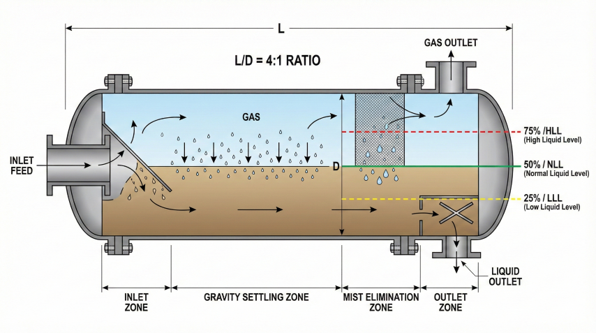
Horizontal separator showing separation zones and liquid level designations.
L/D Ratio Guidelines
Separator Type
Typical L/D Ratio
Rationale
Horizontal 2-phase
3:1 to 5:1
Balance gas residence and vessel cost
Horizontal 3-phase
4:1 to 5:1
Longer for oil-water settling
Vertical separator
2:1 to 4:1
Sufficient liquid surge height
Slug catcher
5:1 to 12:1
Large surge capacity required
Liquid Height Guidelines
Horizontal separator liquid level design:
Normal liquid level (NLL): h/D = 0.5 (half-full) is standard design point
High liquid level (HLL): h/D = 0.75 maximum (trips high-level shutdown)
Working liquid capacity: Volume between LLL and HLL (typically 50% of total liquid space)
Surge capacity: Volume between NLL and HLL (absorbs flow rate variations)
Liquid Volume Calculation - Vertical Separator
Vertical Vessel Liquid Volume:
V = (π/4) × D² × h_liquid
Where:
V = Liquid volume (ft³)
D = Inside diameter (ft)
h_liquid = Height of liquid section (ft)
Vertical separator sections:
1. Gas separation zone (top): h_gas = 4 ft minimum
2. Liquid collection zone (middle): h_liquid = V_required / (π/4 × D²)
3. Sump zone (bottom): h_sump = 1–2 ft for level control
Total height: H_total = h_gas + h_liquid + h_sump + head heights
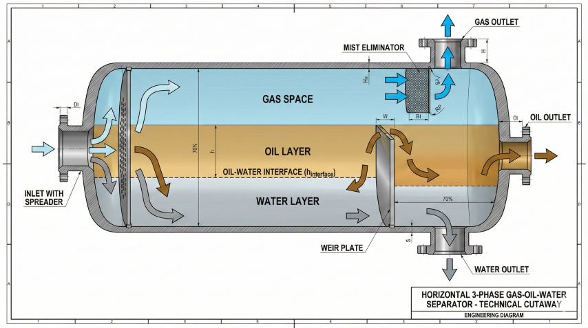
Three-phase separator showing oil-water interface control via weir plate.
3-Phase Separator Oil-Water Interface
Weir Height Calculation (3-Phase Horizontal):
h_weir = h_WLL + (P_atm × 2.31) × [(SG_oil - SG_gas) / (SG_water - SG_oil)]
Where:
h_weir = Weir height above vessel bottom (inches)
h_WLL = Water liquid level at weir (inches)
P_atm = Atmospheric pressure head (ft or psi)
SG = Specific gravities
Oil-water interface stability:
- Difference in SG > 0.05: Good separation
- Difference in SG < 0.02: Difficult separation, may require chemical treatment
Spreader plate or oil skimmer improves oil-water separation.
Surge Volume Design
Additional capacity to handle flow rate variations and slugging:
Service
Surge Time
Multiplier on Retention Time
Steady production
5–10 minutes
1.0× (no extra surge)
Intermittent slugging
10–20 minutes
1.5–2.0×
Severe slugging
20–30 minutes
3.0–5.0×
Well testing
30+ minutes
5.0–10.0×
Design trade-off: Increasing retention time improves separation efficiency and provides surge capacity, but increases vessel size and cost. Most designs use minimum retention time + 50% surge capacity as a practical compromise.
Liquid Capacity Sizing Approach
The liquid capacity sizing procedure ensures adequate retention time:
Liquid Capacity Sizing Steps:
1. Convert liquid flow rate to consistent units (bbl/min or ft³/min)
2. Calculate required liquid volume: V_required = Q_liquid × t_retention
3. For horizontal vessels at half-full (h/D = 0.5):
Solve for length using: V = L × π × D² / 8
4. Check L/D ratio against guidelines (typically 3:1 to 5:1)
- If L/D is too low, increase length to meet minimum ratio
- This often provides additional retention time (margin/surge)
5. Verify both gas AND liquid constraints are satisfied
- The larger of the two governs final vessel size
Key insight: For moderate liquid rates, L/D ratio requirements often
govern vessel length, providing retention time well above minimum.
For high liquid rates, retention time may govern, requiring longer vessels.
4. Internals & Equipment
Separator internals enhance separation efficiency, prevent re-entrainment, and protect downstream equipment. Proper selection and sizing of internals is critical to separator performance.
Corrugated vanes spread flow evenly across vessel cross-section.
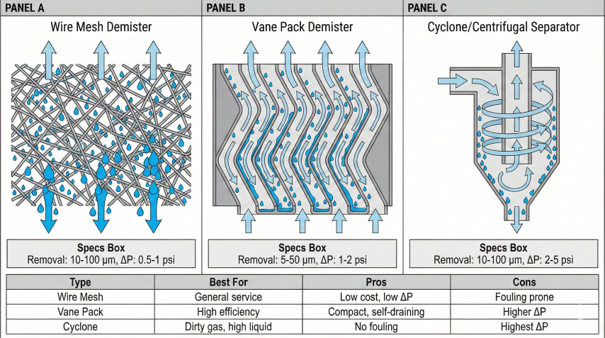
Common mist eliminator types: wire mesh, vane pack, and centrifugal designs.
Mist Eliminators
Type
Droplet Removal
Pressure Drop
Applications
Wire mesh pad
10–100 micron
0.5–1.0 psi
General purpose, most common
Vane pack
5–50 micron
1.0–2.0 psi
High efficiency, compact
Centrifugal (cyclone)
10–100 micron
2.0–5.0 psi
High liquid loading, dirty gas
Coalescing filter
0.1–10 micron
2.0–10 psi
Ultra-high purity, instrument air
Wire Mesh Mist Eliminator Design
Mesh Pad Specifications:
Mesh pad thickness: 4–6 inches (100–150 mm) standard
Wire diameter: 0.006–0.011 inches (0.15–0.28 mm)
Density: 9–12 lb/ft³ (144–192 kg/m³)
Void fraction: 97–99%
Velocity limit through mesh uses Souders-Brown equation with
K-factor specific to mesh pad design. If gas velocity exceeds
the limit, liquid re-entrainment occurs (flooding).
Pressure drop:
ΔP_mesh = 0.5–1.0 psi (clean mesh)
ΔP_mesh increases with liquid loading and fouling.
Maintenance: Replace when ΔP > 2× clean ΔP or every 2–5 years.
Mesh pad suppliers (Koch-Glitsch, Sulzer, AMACS) provide specific
K-factor ratings for their products.
Vortex Breaker
Prevents vortex formation at liquid outlet, which can cause gas entrainment in liquid:
Design: Cross-shaped or circular plate installed above liquid outlet nozzle
Horizontal baffles reduce liquid surface turbulence and foam formation:
Wave Breaker Design:
Number of plates: 2–4 horizontal plates
Spacing: 12–18 inches vertical spacing
Perforation: 50% open area (1/2" to 1" holes)
Material: Typically same as vessel material
Function:
- Dampens liquid waves from inlet turbulence
- Prevents foam from rising into gas space
- Improves gas-liquid interface stability
Critical for foaming crudes and high gas velocity applications.
Coalescing Plate Design:
Plate spacing: 0.75–2.0 inches (19–50 mm)
Inclination angle: 45–60° from horizontal (60° typical)
Plate length: 3–6 ft
Material: Stainless steel, coated carbon steel
Enhanced settling velocity:
v_enhanced = v_stokes × (L/S) × sin(θ)
Where:
L = Plate length
S = Plate spacing
θ = Inclination angle
Typical enhancement factor: 5–10× versus open settling
Internals selection: Over-specifying internals (e.g., vane pack where mesh pad suffices) adds unnecessary cost and pressure drop. Under-specifying (e.g., no mist eliminator) leads to carryover and downstream equipment damage. Match internals to process requirements.
Pressure Drop Considerations
Total separator pressure drop impacts system design:
Component
Typical ΔP (psi)
Notes
Inlet nozzle/diverter
0.5–2.0
Depends on inlet velocity
Wire mesh mist eliminator
0.5–1.0
Clean condition
Vane pack mist eliminator
1.0–2.0
Higher efficiency, higher ΔP
Cyclone inlet separator
2.0–5.0
High efficiency but high ΔP
Total separator ΔP
1.0–5.0
Keep < 5 psi to minimize compression cost
5. Design Procedure & Standards
Separator design follows industry standards including API 12J (oil and gas separators) and ASME Section VIII (pressure vessel code). The design procedure ensures both gas and liquid capacity requirements are met.
Step-by-Step Design Procedure
Horizontal 2-Phase Separator Design:
Step 1: Determine design parameters
- Gas flow rate Q_g (scfd or m³/d)
- Liquid flow rate Q_L (bbl/day or m³/d)
- Operating pressure P (psia or kPa)
- Operating temperature T (°F or °C)
- Fluid properties: ρ_G, ρ_L, μ_G, μ_L
Step 2: Calculate gas capacity constraint
- Select K-factor (0.15–0.35 ft/s)
- Calculate v_max = K × √[(ρ_L - ρ_G) / ρ_G]
- Calculate required gas area A_g = Q_g / v_max
- Assume h/D = 0.5, solve for diameter D_gas
Step 3: Calculate liquid capacity constraint
- Select retention time t_r (1–3 min oil, 3–5 min water)
- Calculate required liquid volume V_L = Q_L × t_r
- Assume h/D = 0.5 and L/D = 3–5, solve for diameter D_liquid
- V_L = L × π × D² / 8, with L = (L/D) × D
Step 4: Select diameter
- D_design = maximum of (D_gas, D_liquid)
- Round up to next standard size (12, 16, 20, 24, 30, 36, 42, 48, 60 inches)
Step 5: Calculate length
- From gas capacity: L_gas = A_g / (D × π/4 × (1 - h/D))
- From liquid capacity: L_liquid = 8 × V_L / (π × D²)
- L_design = maximum of (L_gas, L_liquid, 3×D minimum)
- Add 2–3 ft for inlet/outlet nozzles and internals
Step 6: Verify L/D ratio
- Check 3 ≤ L/D ≤ 5 for 2-phase separator
- Adjust if necessary
Step 7: Size nozzles and internals
- Inlet nozzle: v_inlet < 100 ft/s for gas, < 10 ft/s for liquid
- Outlet nozzles: v_outlet < 60 ft/s for gas, < 5 ft/s for liquid
- Mist eliminator: Check v_gas < K_mesh × √[(ρ_L - ρ_G) / ρ_G]
API 12J Key Requirements
Parameter
API 12J Recommendation
K-factor (horizontal with wire-mesh mist eliminator)
0.35–0.50 ft/s (0.107–0.152 m/s)
K-factor (vertical with wire-mesh mist eliminator)
0.167–0.35 ft/s (0.051–0.107 m/s)
Retention time (oil)
1 min minimum for clean oil, 3–5 min for emulsion
Retention time (water)
3–5 min minimum
L/D ratio (horizontal)
3:1 to 4:1
Liquid level (normal)
h/D = 0.5 (half-full)
Mist eliminator thickness
6 inches (150 mm) for wire mesh
Design droplet size
100 micron with mist eliminator, 500 micron without
ASME Section VIII Pressure Vessel Requirements
Design pressure: 1.1× maximum operating pressure or MAWP + 25 psi (whichever is greater)
Design temperature: Maximum operating temperature + 50°F safety margin
Corrosion allowance: 1/8 inch (3.2 mm) typical for carbon steel
Pressure relief: PSV sized for fire case or blocked outlet scenario
Radiography: Full or spot radiography per ASME UW-11
Material: Carbon steel (SA-516 Gr 70), stainless steel (SA-240 304/316) for corrosive service
Heads: 2:1 elliptical heads standard, hemispherical or torispherical optional
Vertical Separator Design Procedure
Vertical Separator Sizing:
Step 1: Calculate diameter from gas capacity
D = √[4 × Q_g / (π × v_max)]
Where v_max from Souders-Brown with K = 0.10–0.15 ft/s.
Step 2: Calculate liquid section height
h_liquid = (4 × V_L) / (π × D²)
Where V_L = Q_L × t_r (retention time volume).
Step 3: Add other sections
- Gas separation zone: h_gas = 4 ft minimum (above liquid level)
- Sump/level control: h_sump = 1–2 ft (below low liquid level)
- Inlet height: Typically at 0.5 × total height
Step 4: Total tangent-to-tangent height
H_tt = h_gas + h_liquid + h_sump
Step 5: Add head heights
H_total = H_tt + 2 × head height (depends on head type)
Step 6: Check L/D ratio
L/D = H_tt / D should be 2–4 for vertical separator.
If L/D > 4, consider horizontal configuration or increase diameter.
3-Phase Separator Additional Considerations
3-phase design requires careful interface control and extended retention time:
Oil retention time: 3–5 minutes (longer than 2-phase due to oil-water interface)
Water retention time: 3–5 minutes (allows water dropout and settling)
Oil-water interface: Maintain stable interface using weir height and level control
Spreader: Install inlet spreader to distribute flow and avoid interface disturbance
Oil skimmer: Use baffled skimmer to collect oil layer cleanly from water surface
Turndown ratio: Design for 2:1 turndown (50% to 100% flow rate)
Nozzle Sizing
Nozzle Diameter Calculation:
d_nozzle = √(4 × Q / (π × v_max))
Velocity limits:
- Gas inlet: v < 100 ft/s (avoid erosion, noise)
- Gas outlet: v < 60 ft/s (avoid mist eliminator damage)
- Liquid inlet: v < 10 ft/s (avoid turbulence)
- Liquid outlet: v < 5 ft/s (avoid vortex formation)
Standard nozzle sizes: 2", 3", 4", 6", 8", 10", 12", 14", 16"
Include nozzle flanges per ASME B16.5 (150#, 300#, 600# ratings).
Common Design Pitfalls
Undersizing for liquid capacity: Meeting gas capacity but insufficient retention time → poor separation
Ignoring surge volume: No capacity for flow upsets → frequent high-level shutdowns
Incorrect K-factor: Using K without mist eliminator when one is installed → oversized vessel
Neglecting L/D ratio: Very short vessel (L/D < 3) → poor gas distribution, channeling
High inlet velocity: Excessive momentum → liquid re-entrainment, foaming
No vortex breaker: Gas entrainment in liquid outlet → downstream pump cavitation
Inadequate nozzle clearance: Nozzles too close to internals → flow disruption
Ignoring 3-phase complexity: Using 2-phase retention time for 3-phase → emulsion carryover
Final design check: Always verify the separator satisfies BOTH gas capacity (settling velocity) AND liquid capacity (retention time) constraints. The larger of the two governs the final vessel size. Confirm L/D ratio falls within acceptable range and add surge capacity for operational flexibility.
Vessel Function Types — Scrubbers and Knockout Drums
Beyond 2-phase and 3-phase production separators, midstream uses two additional vessel functional types optimized for specific service:
Gas scrubber
Mist Elimination
Removes entrained liquid droplets from gas. Liquid is incidental; sized primarily for gas capacity. Typical retention time 0.5-2 min.
Knockout drum
Slug Catching
Protects downstream equipment from liquid slugs. Sized for surge volume and quick gas-liquid disengagement. Typical retention time 1-5 min for slug catching.
Design Output Summary
A complete separator design specification includes:
Typical Separator Specification:
VESSEL DIMENSIONS:
- Inside diameter (standard size per API 12J)
- Seam-to-seam length
- L/D ratio verification
- Head type (typically 2:1 ellipsoidal)
MECHANICAL DESIGN:
- Design pressure (typically 1.1× MAWP + margin)
- Design temperature
- Material specification (e.g., SA-516 Gr 70)
- Corrosion allowance
- Shell and head thickness per ASME VIII
INTERNALS:
- Inlet device type and size
- Mist eliminator type, size, and location
- Weir plate height (3-phase)
- Vortex breaker at liquid outlets
NOZZLES:
- Inlet, gas outlet, liquid outlet(s), drain
- PSV connection, instrument connections
- Level bridle connections
- Manway size and location
PERFORMANCE:
- Gas velocity vs. maximum allowable
- Actual retention time vs. minimum required
- Separation efficiency estimate
Use our separator sizing calculator
to generate complete specifications with all parameters calculated automatically.
6. Worked Design Examples & GPSA Reference Tables
This section provides complete numerical reference material for separator/vessel sizing: GPSA base K-factor table, pressure correction factors across the full operating range (0-1500 psig), expanded retention time guidelines, and two complete worked design examples (a 10 MMscfd 2-phase separator and a 50 MMscfd high-pressure scrubber).
Horizontal separator internals: Inlet device for bulk separation, settling zone for degassing, mist eliminator for fine droplet removal.
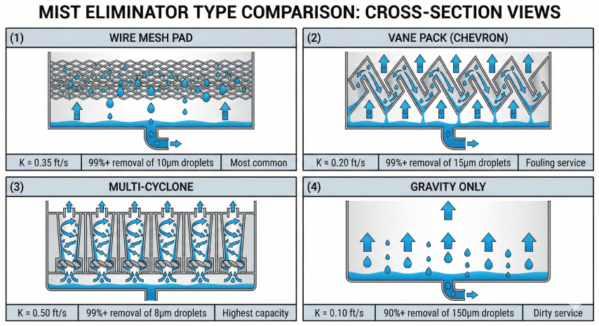
Base K-Factor Values (GPSA Section 7)
Mist Eliminator Type
K-Factor (ft/s)
Droplet Removal
Application
Wire mesh pad (standard)
0.35
99%+ of 10μm droplets
Most common, general service
Wire mesh (high efficiency)
0.40
99%+ of 5μm droplets
Higher capacity, clean service
Multi-cyclone
0.50
99%+ of 8μm droplets
Highest capacity, fouling service
Vane pack (chevron)
0.20
99%+ of 15μm droplets
Fouling/waxy service
Gravity only (no internals)
0.10
90%+ of 150μm droplets
Dirty service, large droplets only
Mist eliminator selection: Wire mesh for general service; vane pack for fouling; multi-cyclone for high capacity.
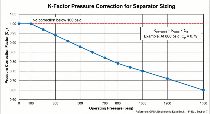
Pressure Correction Factor Table
K-factors decrease at higher pressures due to increased gas density reducing the density difference term. GPSA provides correction factors across the operating range:
Pressure (psig)
Correction Factor
Pressure (psig)
Correction Factor
0 - 100
1.00
700
0.82
200
0.97
800
0.79
300
0.94
900
0.77
400
0.91
1000
0.75
500
0.88
1200
0.71
600
0.85
1500
0.65
Corrected K-Factor:
Kcorrected = Kbase × Cp
Example: Wire mesh at 800 psig
Kcorrected = 0.35 × 0.79 = 0.277 ft/s
This represents a 21% reduction in allowable velocity compared to
low-pressure service, requiring a larger vessel diameter.
K-factor pressure correction: High-pressure separators require larger diameters due to reduced density difference.
Mist Eliminator Selection Guidelines
Wire mesh: Default choice for clean gas service. Low cost, easy maintenance, reliable performance.
Vane pack: Preferred for waxy crude, paraffin deposition, or fouling service. Self-draining design prevents flooding.
Multi-cyclone: Maximum capacity for high gas rate applications. Good for sandy or particulate-laden streams.
No internals: Only for very dirty service or when large droplets (>150μm) dominate. Requires larger vessel.
Flooding risk: Wire mesh pads can flood (liquid accumulation blocks gas flow) if operated above design velocity or with foaming liquids. Design velocity should include 20-25% margin below calculated terminal velocity to prevent flooding during upsets.
Design velocity convention: Always design below terminal velocity to provide margin. Use 75% of Vt for separators (allows for upsets) and 85% for scrubbers (where liquid is incidental).
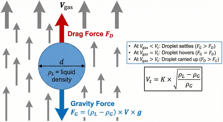
The Souders-Brown equation balances gravity forces (causing droplets to settle) against drag forces (causing droplets to be carried upward with gas flow):
Gravity force: Proportional to droplet volume and density difference (ρL - ρG)
Drag force: Proportional to gas velocity squared and droplet cross-sectional area
At terminal velocity: Forces balance and droplet neither rises nor falls
Droplet settling: At gas velocity below terminal velocity (Vt), gravity dominates and droplets settle out.
Gas Density Calculation (Worked Example)
Gas Density at Operating Conditions:
ρG = (P × M) / (Z × R × T)
Where:
P = Absolute pressure, psia (psig + 14.7)
M = Gas molecular weight = SG × 28.97, lb/lbmol
Z = Compressibility factor (from correlations)
R = Gas constant = 10.73 psia·ft³/(lbmol·°R)
T = Absolute temperature, °R (°F + 460)
Example: Natural gas at 500 psig, 100°F, SG = 0.65
P = 514.7 psia, T = 560°R, M = 18.83 lb/lbmol
Z ≈ 0.92 (from Standing-Katz correlation)
ρG = (514.7 × 18.83) / (0.92 × 10.73 × 560)
ρG = 9,692 / 5,527 = 1.75 lb/ft³
Three-Phase Oil/Water Separation — Stokes Law Worked Example
In three-phase separators, oil and water separate by gravity based on density difference. The settling velocity for water droplets in oil follows Stokes Law:
Stokes Law Settling Velocity:
Vs = g × d² × (ρw - ρo) / (18 × μo)
Where:
Vs = Settling velocity, ft/s
g = Gravitational acceleration = 32.2 ft/s²
d = Droplet diameter, ft
ρw = Water density, lb/ft³
ρo = Oil density, lb/ft³
μo = Oil viscosity, lb/(ft·s)
Example: 200μm water droplet in 30 cp oil, SG = 0.85
d = 200 × 3.28×10⁻⁶ = 6.56×10⁻⁴ ft
ρw = 62.4 lb/ft³, ρo = 53.0 lb/ft³
μo = 30 × 6.72×10⁻⁴ = 0.0202 lb/(ft·s)
Vs = 32.2 × (6.56×10⁻⁴)² × (62.4 - 53.0) / (18 × 0.0202)
Vs = 32.2 × 4.3×10⁻⁷ × 9.4 / 0.364
Vs = 3.6×10⁻⁴ ft/s = 0.022 ft/min
For 2 ft settling distance, time = 2 / 0.022 = 91 minutes
This illustrates why viscous oil requires long retention times or
heated separators to achieve oil/water separation.
Emulsion treatment: Tight water-in-oil emulsions may require chemical demulsifier injection, heat (typically 140-180°F), or electrostatic treaters rather than simply increasing retention time. The calculator assumes reasonable separation; difficult emulsions need specialized equipment.
Given:
Gas flow: 50 MMscfd
Liquid flow: 50 bpd (incidental)
Operating pressure: 1000 psig
Operating temperature: 100°F
Gas gravity: 0.70
Liquid gravity: 0.85 (water = 1)
Mist eliminator: Multi-cyclone (K = 0.50)
Calculation Summary:
Pabs = 1014.7 psia, Tabs = 560°R
M = 0.70 × 28.97 = 20.28 lb/lbmol
Z ≈ 0.86
ρG = (1014.7 × 20.28) / (0.86 × 10.73 × 560) = 4.0 lb/ft³
ρL = 0.85 × 62.4 = 53.0 lb/ft³
Kcorrected = 0.50 × 0.75 = 0.375 ft/s (at 1000 psig)
Vt = 0.375 × √[(53.0 - 4.0) / 4.0] = 0.375 × 3.50 = 1.31 ft/s
Note: High pressure significantly reduces terminal velocity
(compare to 2.27 ft/s at 300 psig)
Qactual = 50×10⁶ × (14.7/1014.7) × (560/520) × 0.86 / 86,400
Qactual = 50×10⁶ × 0.01449 × 1.077 × 0.86 / 86,400
Qactual = 7.76 ft³/s
Gas area (75% available for scrubber):
Agas = 7.76 / (0.85 × 1.31) = 6.97 ft²
Atotal = 6.97 / 0.75 = 9.29 ft²
D = √(4 × 9.29 / π) = 3.44 ft → Round to 3.5 ft (42")
L = 3.5 × 3 = 10.5 ft
Final: D = 3.5 ft (42"), L = 10.5 ft seam-to-seam
L/D Ratio Quality Guidelines (Detailed)
L/D Ratio
Assessment
Notes
< 2.5
Poor
Inadequate gas/liquid separation, maldistribution
2.5 - 4.0
Optimal
Recommended range per GPSA
4.0 - 6.0
Acceptable
May be needed for high liquid loading
> 6.0
Not Recommended
Expensive, difficult to ship, consider parallel vessels
Standard sizes: Select vessel diameter from API 12J standard sizes: 12", 16", 20", 24", 30", 36", 42", 48", 54", 60", 72", 84", 96", 108", 120", 144". Using standard sizes reduces fabrication cost and delivery time.
What is the difference between a 2-phase and 3-phase separator?+
A 2-phase separator separates gas from liquid (oil or water) and is the most common type in production and transmission. A 3-phase separator separates gas, oil, and free water using a weir to control the oil-water interface.
What determines separator sizing — gas capacity or liquid capacity?+
Separator sizing is governed by two independent criteria: gas capacity based on droplet settling velocity, and liquid capacity based on retention time. The vessel must satisfy both requirements simultaneously.
What is the Souders-Brown equation used for in separator design?+
The Souders-Brown equation calculates maximum allowable gas velocity as v_max = K × √[(ρ_L - ρ_G) / ρ_G], where K is an empirical coefficient that depends on vessel orientation, mist eliminator type, and operating pressure. It is the industry standard method per GPSA and API 12J.
What are typical retention times for oil and water in separators?+
Typical retention times are 1–3 minutes for the oil phase, 3–5 minutes for the water phase, and 30–60 seconds minimum for gas residence time.
When should you use a horizontal versus vertical separator?+
Horizontal separators are better for high liquid volumes, foam control, and easier maintenance. Vertical separators have a smaller footprint, handle slugging better, and are preferred for high gas-liquid ratios and offshore platforms where space is constrained.
What role do K-factors play in separator vessel sizing?+
K-factors are pressure-corrected empirical values used in the Souders-Brown equation to account for operating conditions and internals. Base K-factor depends on mist eliminator type (wire mesh 0.35, vane pack 0.20, multi-cyclone 0.50, no internals 0.10) and is then multiplied by a pressure correction factor that decreases from 1.0 at low pressure to about 0.60 at 1500 psig per GPSA Section 7.
What is the difference between a separator, a scrubber, and a knockout drum?+
A separator handles substantial liquid loads with retention time for degassing. A scrubber primarily removes mist from gas (liquid is incidental, K up to 0.85 of Vt). A knockout drum protects downstream equipment from liquid slugs and is sized for surge volume rather than continuous liquid throughput.