Size gas-liquid separators, scrubbers, and knockout drums using the Souders-Brown equation with pressure-corrected K-factors per GPSA Section 7 and API 12J.
Size horizontal two-phase or three-phase separators
Design gas scrubbers and knockout drums
Select appropriate mist eliminator type
Determine vessel dimensions for gas and liquid capacity
1. Separation Fundamentals
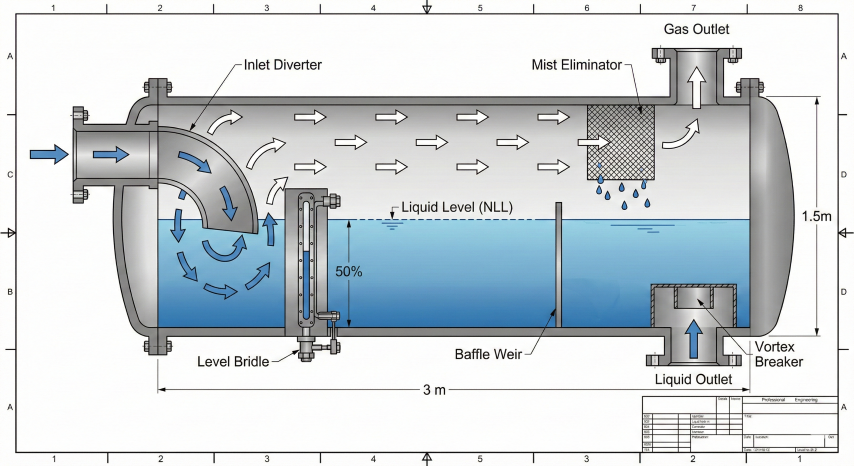
Gas-liquid separation is fundamental to midstream operations. Separators remove liquid droplets from gas streams and disengage gas from liquid. The sizing approach differs based on vessel function and the controlling design criteria.
Horizontal separator internals: Inlet device for bulk separation, settling zone for degassing, mist eliminator for fine droplet removal.
Vessel Types
Two-phase separator
Gas/Liquid
Separates gas from total liquid (oil + water mixed). Most common type in gas gathering systems.
Three-phase separator
Gas/Oil/Water
Separates gas, oil, and water into three streams. Requires longer retention time for oil/water separation.
Gas scrubber
Mist Elimination
Removes entrained liquid droplets from gas. Liquid is incidental; sized primarily for gas capacity.
Knockout drum
Slug Catching
Protects downstream equipment from liquid slugs. Sized for surge volume and quick gas-liquid disengagement.
Sizing Criteria
Separator sizing requires satisfying two independent criteria:
Gas capacity: Vessel diameter must allow gas velocity low enough for liquid droplets to settle out. Governed by Souders-Brown equation.
Liquid capacity: Vessel must hold sufficient liquid volume for required retention time. Governed by liquid flow rate and separation needs.
The final vessel size is determined by whichever criterion requires the larger vessel. For gas-dominated streams (scrubbers), gas capacity typically controls. For liquid-heavy streams (production separators), liquid capacity often controls.
Key concept: Separator sizing is a two-step process. First, calculate minimum diameter from gas capacity using Souders-Brown. Second, calculate minimum volume from liquid retention time. Use the larger requirement, then verify both criteria are satisfied with the final dimensions.
2. Souders-Brown Equation
The Souders-Brown equation determines the maximum allowable gas velocity through a separator. At velocities above this limit, liquid droplets become entrained in the gas stream and carry over to downstream equipment.
Terminal Velocity Equation
Souders-Brown Equation:
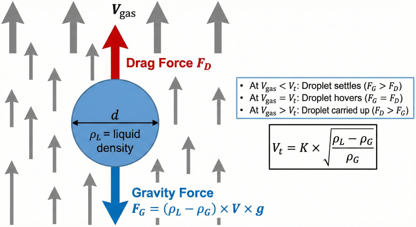
Vt = K × √[(ρL - ρG) / ρG]
Where:
Vt = Terminal (allowable) gas velocity, ft/s
K = Souders-Brown coefficient (empirical), ft/s
ρL = Liquid density, lb/ft³
ρG = Gas density at operating conditions, lb/ft³
This equation is derived from Stokes Law for droplet settling, with
the K-factor incorporating droplet size, drag coefficient, and
equipment geometry empirically.
Physical Basis
The Souders-Brown equation balances gravity forces (causing droplets to settle) against drag forces (causing droplets to be carried upward with gas flow):
Gravity force: Proportional to droplet volume and density difference (ρL - ρG)
Drag force: Proportional to gas velocity squared and droplet cross-sectional area
At terminal velocity: Forces balance and droplet neither rises nor falls
Droplet settling: At gas velocity below terminal velocity (Vt), gravity dominates and droplets settle out.
Gas Density Calculation
Gas Density at Operating Conditions:
ρG = (P × M) / (Z × R × T)
Where:
P = Absolute pressure, psia (psig + 14.7)
M = Gas molecular weight = SG × 28.97, lb/lbmol
Z = Compressibility factor (from correlations)
R = Gas constant = 10.73 psia·ft³/(lbmol·°R)
T = Absolute temperature, °R (°F + 460)
Example: Natural gas at 500 psig, 100°F, SG = 0.65
P = 514.7 psia, T = 560°R, M = 18.83 lb/lbmol
Z ≈ 0.92 (from Standing-Katz correlation)
ρG = (514.7 × 18.83) / (0.92 × 10.73 × 560)
ρG = 9,692 / 5,527 = 1.75 lb/ft³
Vessel Diameter from Gas Capacity
Minimum Diameter Calculation:
Step 1: Calculate actual gas volumetric flow rate
Qactual = Qstd × (Pstd/P) × (T/Tstd) × Z
Where:
Qstd = Standard flow rate (scfd or MMscfd)
Pstd = 14.7 psia, Tstd = 520°R (60°F)
Step 2: Calculate allowable velocity
Vt = K × √[(ρL - ρG) / ρG]
Step 3: Calculate required gas flow area
Agas = Qactual / Vt
Step 4: Calculate diameter (for horizontal vessel at 50% liquid level)
Agas = 0.5 × (π/4) × D²
D = √(8 × Agas / π)
The gas area fraction depends on normal liquid level:
- 50% liquid level: gas occupies 50% of cross-section
- 75% liquid level: gas occupies 25% of cross-section
Design velocity: Always design below terminal velocity to provide margin. Use 75% of Vt for separators (allows for upsets) and 85% for scrubbers (liquid is incidental).
3. K-Factors & Mist Eliminators
The K-factor is an empirical constant that accounts for droplet size, separation efficiency, and equipment internals. GPSA Section 7 provides K-factor values for different mist eliminator types.
Base K-Factor Values (GPSA)
Mist Eliminator Type
K-Factor (ft/s)
Droplet Removal
Application
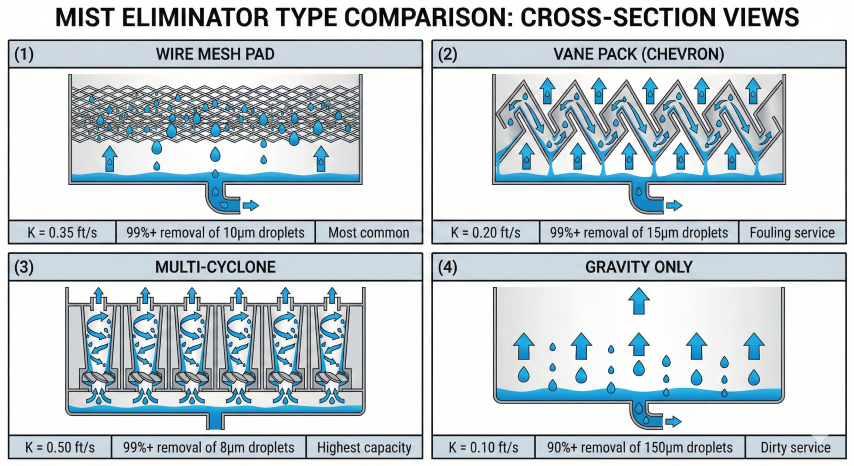
Wire mesh pad (standard)
0.35
99%+ of 10μm droplets
Most common, general service
Wire mesh (high efficiency)
0.40
99%+ of 5μm droplets
Higher capacity, clean service
Multi-cyclone
0.50
99%+ of 8μm droplets
Highest capacity, fouling service
Vane pack (chevron)
0.20
99%+ of 15μm droplets
Fouling/waxy service
Gravity only (no internals)
0.10
90%+ of 150μm droplets
Dirty service, large droplets only
Mist eliminator selection: Wire mesh for general service; vane pack for fouling; multi-cyclone for high capacity.
Pressure Correction Factor
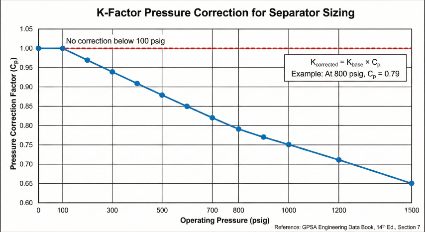
K-factors decrease at higher pressures due to increased gas density reducing the density difference term. GPSA provides correction factors:
Pressure (psig)
Correction Factor
Pressure (psig)
Correction Factor
0 - 100
1.00
700
0.82
200
0.97
800
0.79
300
0.94
900
0.77
400
0.91
1000
0.75
500
0.88
1200
0.71
600
0.85
1500
0.65
Corrected K-Factor:
Kcorrected = Kbase × Cp
Example: Wire mesh at 800 psig
Kcorrected = 0.35 × 0.79 = 0.277 ft/s
This represents a 21% reduction in allowable velocity compared to
low-pressure service, requiring a larger vessel diameter.
K-factor pressure correction: High-pressure separators require larger diameters due to reduced density difference.
Mist Eliminator Selection Guidelines
Wire mesh: Default choice for clean gas service. Low cost, easy maintenance, reliable performance.
Vane pack: Preferred for waxy crude, paraffin deposition, or fouling service. Self-draining design prevents flooding.
Multi-cyclone: Maximum capacity for high gas rate applications. Good for sandy or particulate-laden streams.
No internals: Only for very dirty service or when large droplets (>150μm) dominate. Requires larger vessel.
Flooding risk: Wire mesh pads can flood (liquid accumulation blocks gas flow) if operated above design velocity or with foaming liquids. Design velocity should include 20-25% margin below calculated terminal velocity to prevent flooding during upsets.
4. Liquid Retention Time Sizing
Liquid capacity sizing ensures adequate residence time for gas to disengage from liquid (degassing) and, for three-phase separators, for oil and water to separate by gravity settling.
In three-phase separators, oil and water separate by gravity based on density difference. The settling velocity for water droplets in oil (or oil droplets in water) follows Stokes Law:
Stokes Law Settling Velocity:
Vs = g × d² × (ρw - ρo) / (18 × μo)
Where:
Vs = Settling velocity, ft/s
g = Gravitational acceleration = 32.2 ft/s²
d = Droplet diameter, ft
ρw = Water density, lb/ft³
ρo = Oil density, lb/ft³
μo = Oil viscosity, lb/(ft·s)
Example: 200μm water droplet in 30 cp oil, SG = 0.85
d = 200 × 3.28×10⁻⁶ = 6.56×10⁻⁴ ft
ρw = 62.4 lb/ft³, ρo = 53.0 lb/ft³
μo = 30 × 6.72×10⁻⁴ = 0.0202 lb/(ft·s)
Vs = 32.2 × (6.56×10⁻⁴)² × (62.4 - 53.0) / (18 × 0.0202)
Vs = 32.2 × 4.3×10⁻⁷ × 9.4 / 0.364
Vs = 3.6×10⁻⁴ ft/s = 0.022 ft/min
For 2 ft settling distance, time = 2 / 0.022 = 91 minutes
This illustrates why viscous oil requires long retention times or
heated separators to achieve oil/water separation.
Emulsion treatment: Tight water-in-oil emulsions may require chemical demulsifier injection, heat (typically 140-180°F), or electrostatic treaters rather than simply increasing retention time. The calculator assumes reasonable separation; difficult emulsions need specialized equipment.
Given:
Gas flow: 50 MMscfd
Liquid flow: 50 bpd (incidental)
Operating pressure: 1000 psig
Operating temperature: 100°F
Gas gravity: 0.70
Liquid gravity: 0.85 (water = 1)
Mist eliminator: Multi-cyclone (K = 0.50)
Calculation Summary:
Pabs = 1014.7 psia, Tabs = 560°R
M = 0.70 × 28.97 = 20.28 lb/lbmol
Z ≈ 0.86
ρG = (1014.7 × 20.28) / (0.86 × 10.73 × 560) = 4.0 lb/ft³
ρL = 0.85 × 62.4 = 53.0 lb/ft³
Kcorrected = 0.50 × 0.75 = 0.375 ft/s (at 1000 psig)
Vt = 0.375 × √[(53.0 - 4.0) / 4.0] = 0.375 × 3.50 = 1.31 ft/s
Note: High pressure significantly reduces terminal velocity
(compare to 2.27 ft/s at 300 psig)
Qactual = 50×10⁶ × (14.7/1014.7) × (560/520) × 0.86 / 86,400
Qactual = 50×10⁶ × 0.01449 × 1.077 × 0.86 / 86,400
Qactual = 7.76 ft³/s
Gas area (75% available for scrubber):
Agas = 7.76 / (0.85 × 1.31) = 6.97 ft²
Atotal = 6.97 / 0.75 = 9.29 ft²
D = √(4 × 9.29 / π) = 3.44 ft → Round to 3.5 ft (42")
L = 3.5 × 3 = 10.5 ft
Final: D = 3.5 ft (42"), L = 10.5 ft seam-to-seam
L/D Ratio Guidelines
L/D Ratio
Assessment
Notes
< 2.5
Poor
Inadequate gas/liquid separation, maldistribution
2.5 - 4.0
Optimal
Recommended range per GPSA
4.0 - 6.0
Acceptable
May be needed for high liquid loading
> 6.0
Not Recommended
Expensive, difficult to ship, consider parallel vessels
Standard sizes: Select vessel diameter from API 12J standard sizes: 12", 16", 20", 24", 30", 36", 42", 48", 54", 60", 72", 84", 96", 108", 120", 144". Using standard sizes reduces fabrication cost and delivery time.