The GSP process, developed by Ortloff Engineers in the 1970s, is the most widely adopted cryogenic NGL recovery technology. It uses split-vapor reflux to achieve 85-96% ethane recovery while minimizing compression power through turboexpander energy recovery.
The Gas Subcooled Process (GSP) was developed by Ortloff Engineers (now part of UOP/Honeywell) and patented in the late 1970s (US Patents 4,157,904 and 4,278,457). It represented a significant improvement over conventional turboexpander processes by adding a subcooled reflux stream to the demethanizer column.
Why GSP Dominates NGL Recovery
GSP became the industry standard because it solved a key limitation of conventional expander plants: the loss of valuable ethane and propane to the residue gas stream. By creating a cold, liquid reflux from a portion of the feed gas, GSP captures these components that would otherwise exit the top of the demethanizer.
Recovery improvement
+15-25% ethane
GSP typically recovers 90%+ C2 vs. 70-80% for conventional expander.
Flexible operation
Dual-mode capable
Can switch between ethane recovery and ethane rejection modes.
Energy efficient
Expander power recovery
Turboexpander recovers 40-60% of recompression power requirement.
Proven technology
1000+ installations
Decades of operating experience worldwide.
Key Terminology
Cold separator: Vessel where cooled feed gas separates into vapor and liquid phases before the expander
Split vapor: The fraction of cold separator vapor sent to the subcooler instead of the expander
Subcooler: Heat exchanger that cools the split vapor stream using demethanizer overhead gas
Demethanizer: Fractionation column that separates methane (overhead) from C2+ NGLs (bottoms)
Residue gas: Sales-quality methane stream from demethanizer overhead after recompression
Economic driver: A 100 MMSCFD plant with 6% ethane can produce ~650 BPD additional ethane by using GSP (92% recovery) instead of conventional processing (75% recovery). At $0.50/gal ethane, this represents ~$5 million/year additional revenue.
2. Process Flow Description
The GSP process can be understood as a conventional turboexpander plant with the addition of a subcooled reflux loop. The key innovation is splitting the cold separator vapor and creating a separate cold stream that enters the top of the demethanizer.
Step-by-Step Process Description
GSP Process Steps:1. Feed Gas Preparation
• Inlet separation removes free liquids and water
• Dehydration to <0.1 ppmw H₂O (molecular sieve typical)
• Feed typically at 600-1200 psia, 60-100°F
2. Feed Cooling (Cold Box)
• Feed/residue gas heat exchanger recovers cold from outlet streams
• Propane chiller provides additional cooling (if equipped)
• Feed cooled to -20°F to -60°F depending on inlet richness
3. Cold Separation
• Cold separator at -40°F to -80°F, same pressure as feed
• Vapor exits top (85-95% of feed)
• Liquid (condensed NGLs) exits bottom to demethanizer
4. Vapor Split (The GSP Innovation)
• Cold separator vapor splits into two streams:
- Main stream (60-75%): to turboexpander
- Split stream (25-40%): to subcooler
• Split ratio is key design variable
5. Turboexpander
• Main vapor expands from feed pressure to demethanizer pressure
• Typically 800 psia → 250-350 psia
• Isentropic expansion produces ~80-120°F temperature drop
• Expander shaft drives residue compressor (power recovery)
• Outlet at -130°F to -160°F, enters demethanizer mid-section
6. Subcooler
• Split vapor cooled by demethanizer overhead gas
• Inlet: -40°F to -80°F (cold separator conditions)
• Outlet: -100°F to -140°F (subcooled liquid)
• Subcooled stream throttled through JT valve to demethanizer pressure
• Enters demethanizer at top tray as cold reflux
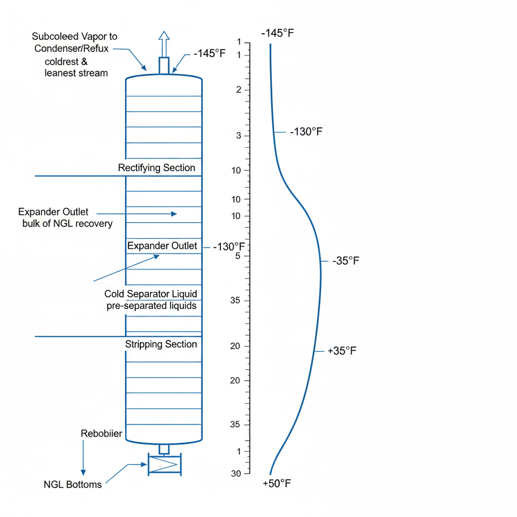
7. Demethanizer
• Fractionation column, 20-40 trays, 250-350 psia
• Three feeds: expander outlet (mid), subcooled reflux (top), cold sep liquid (mid)
• Overhead: methane-rich vapor at -140°F to -160°F
• Bottoms: C2+ NGL product at 40-80°F
8. Residue Compression
• Overhead vapor warmed through cold box exchangers
• Compressed to sales gas pressure (typically 900-1200 psia)
• Expander-driven compressor provides 40-60% of compression
• Electric or gas-driven booster compressor for remainder
Why Split-Vapor Reflux Works
The subcooled reflux stream is the key to GSP's high recovery. When this cold liquid enters the top of the demethanizer, it:
Provides mass transfer driving force: Cold liquid contacts rising vapor, absorbing C2+ components
Shifts equilibrium: Low temperature favors heavier components staying in liquid phase
Increases internal reflux: More liquid flowing down improves separation efficiency
Reduces overhead C2 loss: Ethane that would exit in overhead is captured by cold reflux
Demethanizer Column with GSP Feed Locations - Subcooled reflux, expander outlet, and cold separator liquid entry points with temperature profile
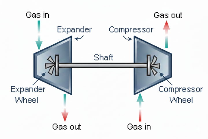
The turboexpander is the heart of the GSP process. It converts the pressure energy of the gas into shaft work while producing the deep cooling required for NGL condensation.
Turboexpander Design Equations:Isentropic Temperature Change:
T₂ᵢₛ = T₁ × (P₂/P₁)^((k-1)/k)
Where:
T = Temperature (°R absolute)
P = Pressure (psia)
k = Cp/Cv ratio (~1.28 for natural gas)
Actual Temperature Change with Efficiency:
ΔT_actual = η × (T₁ - T₂ᵢₛ)
T₂_actual = T₁ - ΔT_actual
Where η = isentropic efficiency (typically 0.82-0.88)
Power Recovery:
W = ṁ × Cp × ΔT_actual
Where:
W = Power (BTU/hr)
ṁ = Mass flow (lb/hr)
Cp = Heat capacity (~0.52 BTU/lb·°F)
HP = W / 2545
Example: 65 MMSCFD at 800 psia, -72°F to 280 psia
T₁ = -72 + 459.67 = 387.67 °R
P₂/P₁ = 280/800 = 0.35
k = 1.28, exponent = 0.28/1.28 = 0.21875
T₂ᵢₛ = 387.67 × (0.35)^0.21875 = 387.67 × 0.795 = 308.2 °R = -151.5°F
ΔT_isentropic = -72 - (-151.5) = 79.5°F
At η = 0.85:
ΔT_actual = 0.85 × 79.5 = 67.6°F
T₂_actual = -72 - 67.6 = -139.6°F
Mass flow = 65 × 10⁶ / 24 × 19.5 / 379.5 = 139,200 lb/hr
Power = 139,200 × 0.52 × 67.6 = 4.89 × 10⁶ BTU/hr = 1,921 HP
Subcooler Heat Exchanger
The subcooler is typically a brazed aluminum plate-fin heat exchanger due to the cryogenic temperatures and close temperature approaches required.
Subcooler Design:Heat Balance:
Q = ṁ_split × Cp × (T_in - T_out)
LMTD Calculation:
Hot side: Split vapor cooling from -72°F to -120°F
Cold side: Demethanizer overhead warming from -155°F to -85°F
ΔT₁ = -72 - (-85) = 13°F (hot end)
ΔT₂ = -120 - (-155) = 35°F (cold end)
LMTD = (35 - 13) / ln(35/13) = 22 / 0.99 = 22.2°F
Area Calculation:
A = Q / (U × LMTD)
Where U = 80-150 BTU/hr·ft²·°F for gas/gas in BAHX
Example: 35 MMSCFD split stream
ṁ = 35 × 10⁶ / 24 × 19.5 / 379.5 = 74,900 lb/hr
Q = 74,900 × 0.52 × (120-72) = 1.87 × 10⁶ BTU/hr
At U = 100 BTU/hr·ft²·°F:
A = 1.87 × 10⁶ / (100 × 22.2) = 842 ft²
Demethanizer Column
The demethanizer separates methane from C2+ components. GSP demethanizers have unique characteristics due to the multiple feed locations and cold reflux.
Parameter
Typical Range
Notes
Operating pressure
250-350 psia
Lower pressure improves C1/C2 separation but increases recompression
Top temperature
-140°F to -165°F
Set by reflux temperature and column pressure
Bottom temperature
40°F to 80°F
Set by C2 specification in NGL product
Number of trays
20-40
Sieve or valve trays; more trays = better separation
Reflux ratio
0.3-0.6
GSP uses cold external reflux vs. hot internal reflux
Reboiler duty
5-15 MMBTU/hr
Steam, hot oil, or process heat; maintains bottoms temp
Residue Gas Compressor
The residue compressor raises the demethanizer overhead pressure to pipeline sales pressure. In GSP plants, this is typically a two-stage system:
First stage (expander-driven): Directly coupled to turboexpander shaft; provides 40-60% of total compression
Second stage (motor or gas turbine): Booster compressor for remainder of compression duty
Turboexpander-Compressor Assembly - Cutaway view showing expander wheel, compressor wheel, magnetic bearings, and seal system
4. Design Parameters
Split Ratio Optimization
The split ratio (fraction of cold separator vapor to expander vs. subcooler) is the most critical design variable in GSP. Higher subcooler flow improves recovery but reduces expander power recovery.
Expander Split
Subcooler Split
C2 Recovery
C3 Recovery
Expander Power
80%
20%
85-88%
96-98%
High
70%
30%
88-92%
98-99%
Medium-High
65%
35%
90-94%
99%
Medium
60%
40%
92-95%
99.2%
Medium-Low
55%
45%
94-96%
99.5%
Low
Temperature Levels
GSP plant temperatures must be carefully designed to achieve target recovery while avoiding operational issues.
Critical Temperature Points:Cold Separator Temperature:
• Determines amount of liquid condensed before expander
• Typical: -40°F to -80°F
• Lower temperature = more liquid = less vapor to expander
• Set by feed/residue exchanger and any external refrigeration
Subcooler Outlet Temperature:
• Determines quality of reflux to demethanizer
• Typical: -100°F to -140°F
• Lower temperature = better reflux quality = higher recovery
• Limited by demethanizer overhead temperature (cold utility)
Expander Outlet Temperature:
• Coldest point in the process
• Typical: -130°F to -165°F
• Set by expansion ratio and inlet conditions
• Determines demethanizer top temperature
Temperature Approach in Subcooler:
ΔT_approach = T_subcooler_out - T_deC1_overhead
• Typical: 5-15°F
• Closer approach = larger exchanger = higher cost
• Too close approach risks freeze-up at turndown
Pressure Selection
Key Pressure Decisions:Feed Pressure:
• Higher pressure = more expansion work available
• Higher pressure = worse C1/C2 separation (K-values closer)
• Typical: 600-1200 psia
• Often set by upstream pipeline or well pressure
Demethanizer Pressure:
• Lower pressure = better C1/C2 separation
• Lower pressure = more recompression required
• Lower pressure = colder top temperature (may cause CO₂ freeze)
• Typical: 250-350 psia
• Optimize based on recovery target vs. power cost
Expansion Ratio:
ER = P_inlet / P_outlet = 600-1200 / 250-350 = 2-4:1
Higher ER = more cooling, more power recovery, but diminishing returns above ~3.5:1
Residue Sales Pressure:
• Set by pipeline requirements
• Typical: 800-1200 psia
• Higher sales pressure = more compression power
Operating Constraints
Hydrate formation: Feed must be dehydrated to <0.1 ppmw H₂O. Hydrates form at ~32°F at high pressure and plug exchangers/piping.
CO₂ freeze-out: Solid CO₂ forms below -70°F to -100°F depending on concentration and pressure. CO₂ content typically limited to <2% for GSP plants; remove CO₂ upstream if higher.
Metallurgy: Temperatures below -20°F require impact-tested carbon steel or stainless steel. Cryogenic service (<-50°F) typically uses 304/316 SS or aluminum.
Turndown: GSP plants can typically turn down to 50-60% of design rate. Below this, heat exchanger approaches become too close and expander efficiency drops.
Design tip: For preliminary design, assume 65% expander split, -100°F subcooler outlet, and 300 psia demethanizer pressure. This gives ~91% C2 recovery with reasonable power consumption. Optimize from there based on economic analysis.
5. Process Variants
Several enhanced processes have been developed to achieve higher recovery than standard GSP, or to provide operational flexibility.
Recycle Split Vapor (RSV)
RSV adds a small recycle stream from the residue gas to create additional reflux. This achieves 97-99% ethane recovery.
RSV Concept
Residue gas recycle
A portion of compressed residue gas is cooled and returned to the demethanizer top as supplemental reflux, providing colder reflux than GSP alone.
Recovery
97-99% C2
Near-complete ethane recovery with modest additional power consumption.
Cold Residue Recycle (CRR)
CRR uses a larger recycle stream and additional cooling to achieve maximum recovery. Best suited for very high ethane value scenarios.
Dual-Mode Operation
GSP plants can operate in either ethane recovery or ethane rejection mode by adjusting operating parameters:
Parameter
Ethane Recovery Mode
Ethane Rejection Mode
Demethanizer pressure
250-300 psia
350-450 psia
Subcooler split
30-40%
15-25%
Reboiler temperature
40-60°F
80-100°F
C2 recovery
90-96%
10-30%
C3 recovery
99%+
90-98%
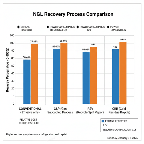
Comparison of NGL Recovery Technologies
Technology
C2 Recovery
C3 Recovery
Complexity
Capital Cost
Conventional expander
70-80%
90-95%
Low
Low
GSP (standard)
85-96%
98-99%
Medium
Medium
RSV
97-99%
99.5%
Medium-High
Medium-High
CRR
98-99.5%
99.8%
High
High
IPSI-1 / IPSI-2
97-99%
99.5%
High
High
NGL Recovery Technology Comparison - Ethane and propane recovery with power consumption for Conventional, GSP, RSV, and CRR processes
Selection guidance: GSP is the right choice for most projects targeting 85-96% ethane recovery. For higher recovery (>96%), consider RSV or CRR variants. For propane recovery only (ethane rejection), conventional expander or modified GSP operation may be sufficient.
The GSP is a cryogenic NGL recovery process that uses split-vapor reflux and turboexpander technology to achieve high ethane and heavier hydrocarbon recovery.
What is the role of the demethanizer in the GSP process?+
The demethanizer column separates methane from heavier NGL components by using cryogenic temperatures and reflux from the subcooled feed.
What reference covers GSP design fundamentals?+
GSP design fundamentals are covered in GPSA Engineering Data Book Section 16.