1. Mercury in Natural Gas
Mercury occurs naturally in reservoir fluids from geological formations. Concentrations vary by orders of magnitude between regions—from <0.1 µg/Nm³ in North American dry gas to >500 µg/Nm³ in Southeast Asian fields.
Mercury Species
Mercury in natural gas exists primarily as elemental vapor (Hg⁰), with trace amounts of organomercury compounds and mercuric salts:
| Species | Formula | Occurrence | Removal |
|---|---|---|---|
| Elemental mercury | Hg⁰ | 95-99% of total | Easy (adsorption) |
| Mercuric chloride | HgCl₂ | Trace in sour gas | Moderate |
| Dimethyl mercury | (CH₃)₂Hg | Rare (biogenic) | Difficult |
Regional Mercury Levels
| Region | Typical Range (µg/Nm³) | Comments |
|---|---|---|
| North America (onshore) | 0.01–0.5 | Generally low; some exceptions |
| North Sea | 0.1–10 | Variable by field |
| Indonesia/Malaysia | 50–500 | High mercury province |
| Middle East | 1–50 | Moderate levels |
| Australia (NW Shelf) | 0.5–20 | Variable |
2. Failure Mechanism
Mercury causes liquid metal embrittlement (LME) of aluminum alloys used in brazed aluminum heat exchangers (BAHX). This is the primary driver for mercury removal in LNG facilities.
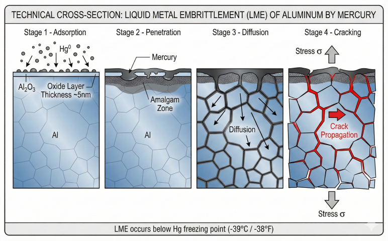
LME Process
- Adsorption: Mercury vapor condenses on cold aluminum surfaces
- Amalgamation: Mercury penetrates oxide layer, forms Al-Hg amalgam
- Diffusion: Mercury migrates along grain boundaries
- Embrittlement: Amalgam weakens grain boundary cohesion
- Cracking: Under normal operating stress, intergranular cracks form
- Failure: Catastrophic rupture of heat exchanger passages
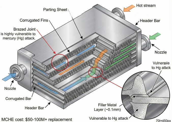
Equipment at Risk
- Main cryogenic heat exchangers (MCHE): $50-100M+ replacement cost
- Cold boxes: Brazed aluminum plate-fin exchangers
- Kettle reboilers: Aluminum tubes in LNG/NGL service
- Cryogenic piping: Aluminum alloy sections
3. Removal Technologies
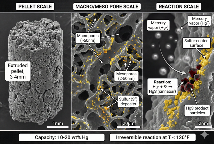
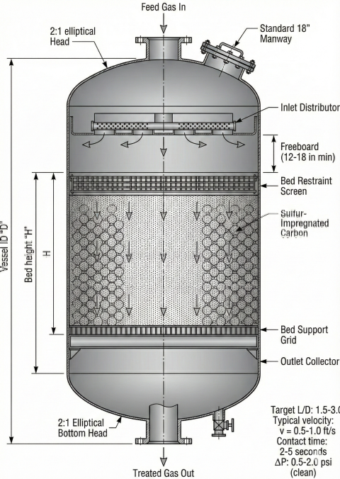
Mercury removal relies on chemical reaction between mercury vapor and solid adsorbents. The dominant technology is sulfur-impregnated activated carbon.
Sulfur-Impregnated Carbon
Activated carbon impregnated with 10-15% elemental sulfur. Mercury reacts irreversibly with sulfur to form stable mercuric sulfide (HgS, cinnabar):
Adsorbent Comparison
| Adsorbent | Hg Capacity | Max Temp | Regenerable | Relative Cost |
|---|---|---|---|---|
| Sulfur-impregnated carbon | 10-20 wt% | 120°F (50°C) | No | 1.0× |
| Metal sulfide (CuS/ZnS) | 5-10 wt% | 300°F (150°C) | Some types | 1.5-2.0× |
| Silver-impregnated carbon | 8-15 wt% | 100°F (38°C) | No | 5-10× |
Process Configurations
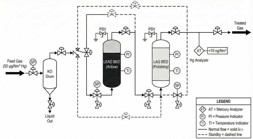
- Single guard bed: One vessel, full changeout at breakthrough. Suitable for low Hg (<5 µg/Nm³)
- Lead-lag (recommended): Two vessels in series. Lead saturates first; rotate to maximize utilization (80-90%)
- Multi-stage: Bulk removal (metal sulfide) + carbon polishing. For high Hg (>100 µg/Nm³)
4. Bed Sizing Methods
MRU sizing uses material balance for adsorbent quantity and contact time/velocity limits for vessel dimensions. Both constraints must be satisfied.
Material Balance Method
Contact Time Requirement
Vessel Sizing
Design Parameters Summary
| Parameter | Typical Range | Design Basis |
|---|---|---|
| Superficial velocity | 0.5-1.0 ft/s | Prevent fluidization |
| Contact time | 2-5 seconds | Reaction equilibrium |
| L/D ratio | 1.5:1 to 3:1 | Flow distribution |
| Pressure drop (clean) | 0.5-2.0 psi | Process constraints |
| Utilization factor | 0.7-0.9 | MTZ, channeling allowance |
5. Industry Specifications
LNG Plant Feed Gas
| Project/Region | Mercury Limit | Basis |
|---|---|---|
| Typical LNG specification | <10 ng/Nm³ | BAHX protection |
| Australia (Gorgon, Wheatstone) | <1 ng/Nm³ | Conservative design |
| Qatar LNG | <10 ng/Nm³ | Industry standard |
| US Gulf Coast LNG | <10 ng/Nm³ | FERC/DOE permits |
Pipeline Specifications
| Pipeline System | Mercury Limit |
|---|---|
| US interstate (typical) | 30 µg/Nm³ (0.001 gr/100 scf) |
| European grid | 100 ng/Nm³ |
| Offshore gathering | No formal limit (case-by-case) |
Mercury Measurement
Accurate measurement is critical for compliance verification and breakthrough detection:
| Method | Detection Limit | Application |
|---|---|---|
| ASTM D6350 (gold trap + AAS) | ~0.5 ng/Nm³ | Reference method |
| ASTM D5954 (AFS) | ~0.1 ng/Nm³ | Ultra-low detection |
| Online CVAF analyzer | 0.01-100 µg/Nm³ | Continuous monitoring |
| Portable gold film | ~1 ng/m³ | Spot checks |
6. Operations & Changeout
Breakthrough Curve
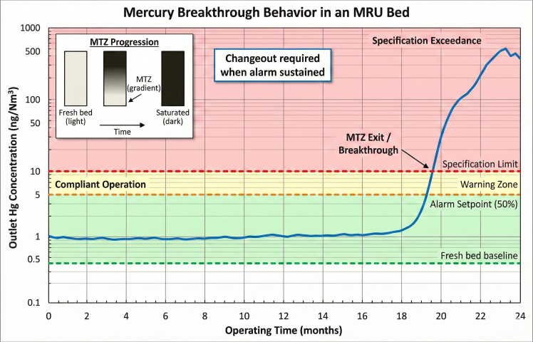
Lead-Lag Changeout Strategy
- Normal operation: Lead vessel online (bulk removal), lag vessel polishing
- Approach breakthrough: When lead outlet reaches 50% of spec, monitor closely
- Lead breakthrough: Isolate lead vessel when outlet exceeds spec
- Rotation: Lag becomes new lead; change out spent lead vessel
- Reload: Fresh adsorbent in former lead vessel; becomes new lag
Changeout Safety
Spent mercury adsorbent is hazardous waste (EPA RCRA). Changeout requires:
- Vessel isolation: Blind flanges, nitrogen purge to <1% LEL
- Personnel protection: Supplied air respirators, Tyvek suits
- Mercury monitoring: Continuous vapor monitoring (OSHA PEL: 0.1 mg/m³)
- Vacuum transfer: Enclosed transfer to sealed containers
- Disposal: Manifested transport to licensed hazardous waste facility
Spent Adsorbent Disposal
| Method | Process | Cost ($/tonne) |
|---|---|---|
| Stabilization + landfill | Cement/polymer encapsulation | 500-1,500 |
| Thermal retort | Heat to recover Hg | 2,000-5,000 |
| Chemical treatment | Leach and precipitate | 3,000-8,000 |
Ready to use the calculator?
→ Launch Calculator