1. Overview & Applications
Molecular sieves are synthetic crystalline aluminosilicates (zeolites) with uniform pore structures that selectively adsorb molecules based on size and polarity. For natural gas dehydration, molecular sieves achieve outlet dew points of -100°F to -150°F—far beyond glycol dehydration capabilities.
LNG Feedstock
<0.1 ppmv H₂O
Required to prevent ice formation in cryogenic exchangers at -260°F.
NGL Recovery
Prevent hydrate formation in turboexpander and demethanizer.
Pipeline Spec
7 lb H₂O/MMscf
Typical spec; mol sieves easily achieve <1 lb/MMscf.
Glycol vs Mol Sieve
TEG limited to ~7 lb/MMscf; mol sieves required for deeper drying.
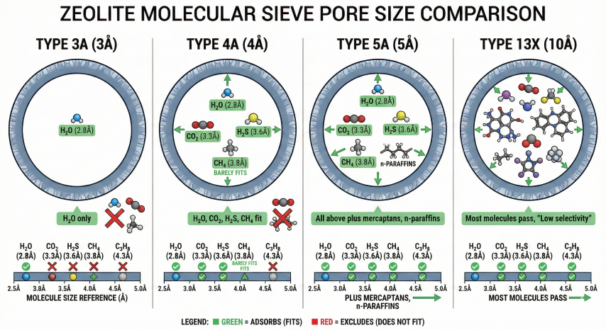
2. Zeolite Type Selection
Zeolite type selection depends on feed gas composition and what contaminants (beyond water) need to be removed. The pore size determines which molecules can enter and be adsorbed.
| Type | Pore (Å) | Adsorbs | Excludes | Primary Application |
|---|---|---|---|---|
| 3A | 3 | H₂O, NH₃ | CO₂, H₂S, C₂+ | Water-only removal; rich gas with high C₃+ |
| 4A | 4 | H₂O, CO₂, H₂S | C₃+, aromatics | Most common for NG; combined H₂O + acid gas |
| 5A | 5 | H₂O, CO₂, H₂S, mercaptans | iso-paraffins, C₅+ | Sour gas with mercaptans; high water loading |
| 13X | 10 | H₂O, CO₂, H₂S, all HC | Large molecules | Bulk acid gas removal; less selective |
Selection Guidelines
- Type 3A: Use when inlet gas has high C₃+ content and you want water removal ONLY. Prevents hydrocarbon co-adsorption that would contaminate regeneration gas and reduce bed life.
- Type 4A: Standard choice for most natural gas applications. Removes water + CO₂ + H₂S simultaneously. Most cost-effective for sweet to moderately sour gas.
- Type 5A: Required when mercaptans (RSH) must be removed along with water. Higher capacity than 4A but co-adsorbs more hydrocarbons.
- Type 13X: Use for bulk CO₂ removal upstream of a 4A polishing bed. Not recommended as primary dehydration sieve due to low selectivity.
Physical Properties
| Property | 3A | 4A | 5A | 13X |
|---|---|---|---|---|
| Bulk density (lb/ft³) | 43 | 42 | 41 | 40 |
| Water capacity @ 77°F (wt%) | 20 | 22 | 21.5 | 28 |
| Bead size (mesh) | 8×12 | 8×12 | 8×12 | 8×12 |
| Max regen temp (°F) | 600 | 600 | 600 | 600 |
| Heat capacity (Btu/lb·°F) | 0.22 | 0.22 | 0.22 | 0.23 |
3. Adsorption Fundamentals
Molecular sieve adsorption is driven by strong electrostatic interaction between polar water molecules and the ionic framework of the zeolite. The adsorption is highly exothermic, releasing ~1800 Btu/lb water adsorbed.
Dynamic Capacity
Design capacity is less than equilibrium capacity due to temperature effects, relative saturation, and safety factors. GPSA Figure 20-37 provides capacity correction curves.
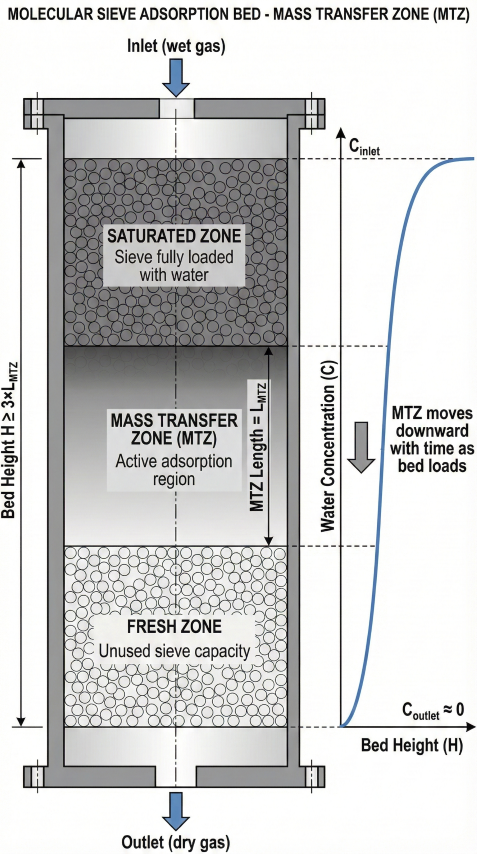
Mass Transfer Zone (MTZ)
The MTZ is the region of the bed where water concentration transitions from saturated (inlet) to fresh (outlet) sieve. Bed height must exceed 2-3× MTZ length to prevent premature breakthrough.
Co-Adsorption Effects
Type 4A and 5A sieves co-adsorb other components, which reduces water capacity and complicates regeneration.
| Component | 3A | 4A | 5A | Impact |
|---|---|---|---|---|
| CO₂ | No | Yes (~10%) | Yes (~12%) | Reduces H₂O capacity 2-5% |
| H₂S | No | Yes (~6%) | Yes (~8%) | Difficult to regenerate; fouls bed |
| Mercaptans | No | Partial | Yes | Irreversible adsorption; poisons bed |
| Heavy HC (C₆+) | No | No | Partial | Deposits in pores; use 3A if high C₆+ |
4. Bed Sizing Method
Bed sizing involves calculating required sieve mass from water loading, then determining vessel dimensions from velocity constraints and volume requirements.
Step 1: Water Loading per Cycle
Step 2: Required Sieve Mass
Step 3: Vessel Diameter from Velocity
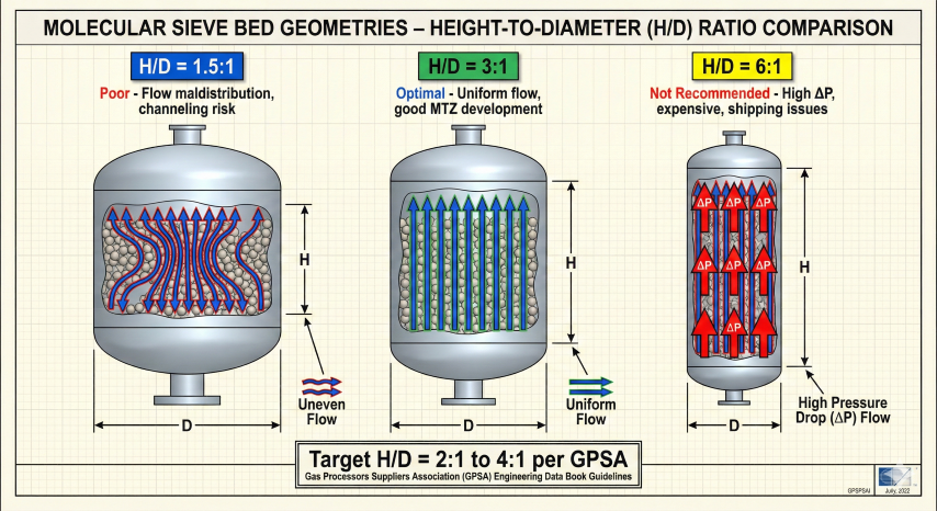
Step 4: Bed Height and H/D Ratio
Pressure Drop
Pressure drop through packed beds is calculated using the Ergun equation. Design ΔP typically ranges from 5-15 psi.
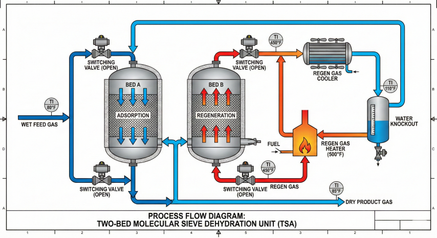
5. TSA Regeneration Cycle
Thermal Swing Adsorption (TSA) regenerates molecular sieves by heating to 450-550°F with dry regeneration gas, desorbing water vapor. The complete cycle includes depressurization, heating, cooling, and repressurization.
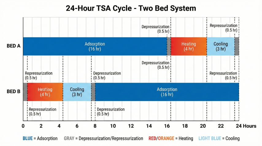
Cycle Steps
| Step | Duration | Conditions | Purpose |
|---|---|---|---|
| 1. Adsorption | 8-24 hr | Process P&T; gas flows down | Remove water from feed gas |
| 2. Depressurization | 0.5 hr | Vent to flare/recovery | Reduce P for regen; recover inventory |
| 3. Heating | 3-5 hr | 450-550°F regen gas; flow up | Desorb water from sieve |
| 4. Cooling | 2-4 hr | Ambient dry gas; flow up | Cool bed to <150°F for adsorption |
| 5. Repressurization | 0.5 hr | Dry product gas | Equalize with operating bed |
Regeneration Gas Requirements
Temperature Limits
Multi-Bed Configurations
| Configuration | Beds | Mode | Best For |
|---|---|---|---|
| Two-bed | 2 | 1 ads, 1 regen | Simple, low cost; long cycles (16-24 hr) |
| Three-bed | 3 | 2 ads, 1 regen | Smaller beds; short cycles (8-12 hr) |
| Four-bed | 4 | 2-3 ads, 1 regen | Large plants; redundancy; maintenance flexibility |
6. Operations & Troubleshooting
Monitoring Parameters
- Outlet dew point: Primary indicator of bed performance; alarm if rises above target
- Bed temperatures: Install 6-12 thermocouples at different heights; monitor during regen
- Pressure drop: Track over time; increase indicates fouling or fines migration
- Regeneration gas temperature: Ensure reaching 450-550°F throughout bed
Common Problems
| Problem | Symptoms | Likely Cause | Solution |
|---|---|---|---|
| Premature breakthrough | Water in product before cycle end | Incomplete regen; channeling; fouling | Increase regen temp/time; inspect bed |
| High ΔP | ΔP > 20 psi; compressor issues | Fines migration; liquid carryover | Install upstream filters; knock out liquids |
| Reduced capacity | Shorter cycle times over months | Bed aging; irreversible adsorption | High-temp regen; plan bed replacement |
| Bed dusting | Fines in downstream equipment | Thermal stress; mechanical damage | Limit regen rate; install outlet screen |
Bed Life Expectations
Expected service life depends on operating severity:
- Clean, sweet gas: 5-7 years
- Moderately sour gas: 4-5 years
- Heavy HC or mercaptans: 3-4 years
- High cycling or upsets: 2-4 years
Replace when capacity drops below 80% of design or when mechanical issues (dusting, high ΔP) develop.
Ready to use the calculator?
→ Launch Calculator