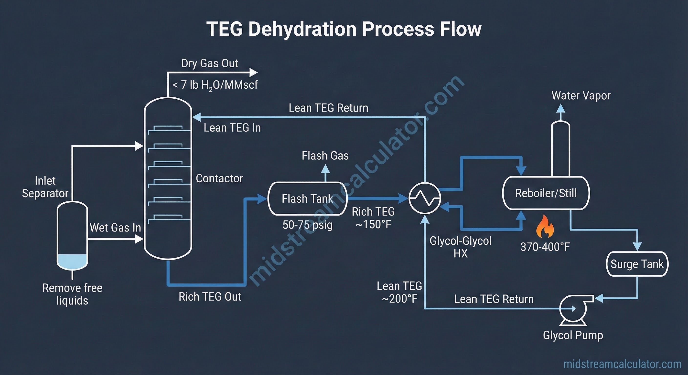
1. Process Overview
Glycol dehydration uses liquid glycol (typically TEG) to absorb water vapor from natural gas. The process operates in a continuous loop: lean glycol contacts wet gas in the contactor, absorbs water, then flows to the regenerator where heat drives off the water. The reconcentrated lean glycol returns to the contactor.
Why Dehydrate?
- Hydrate prevention: Water + gas form ice-like solids that plug pipelines
- Corrosion control: Liquid water causes internal corrosion
- Pipeline spec: Tariffs require <7 lb H₂O/MMscf (≈112 ppmv)
- Downstream protection: Cryogenic plants require <1 ppmv
2. Glycol Properties
TEG — The Industry Standard
Triethylene glycol (TEG) dominates gas dehydration due to its low vapor pressure, high water affinity, and thermal stability up to 400°F.
| Property | Value | Units | Source |
|---|---|---|---|
| Molecular Formula | C₆H₁₄O₄ | — | — |
| Molecular Weight | 150.2 | g/mol | GPSA Fig 6.3 |
| Density (77°F/25°C) | 1.119 | g/cc | GPSA Fig 6.3 |
| Density (77°F) | 9.34 | lb/gal | GPSA Fig 6.3 |
| Boiling Point (1 atm) | 545.9 | °F | GPSA Fig 6.3 |
| Freezing Point (pure) | 19 | °F | GPSA Fig 6.3 |
| Viscosity (77°F) | 37.3 | cP | GPSA Fig 6.3 |
| Specific Heat (77°F) | 0.53 | BTU/lb·°F | GPSA Fig 6.3 |
| Thermal Decomposition | 404 | °F | GPSA/Industry |
| Lean Concentration | 98.5–99.5 | wt% | Design std |
| Rich Concentration | 95–97 | wt% | Design std |
TEG Advantages
- Low vapor pressure: Minimal glycol losses to gas stream (0.01–0.05 gal/MMscf typical)
- High regeneration: Can achieve 98.5–99.5% purity without stripping gas
- Thermal stability: Safe operation up to 400°F
- Deep drying: Capable of <4 lb H₂O/MMscf outlet with proper design
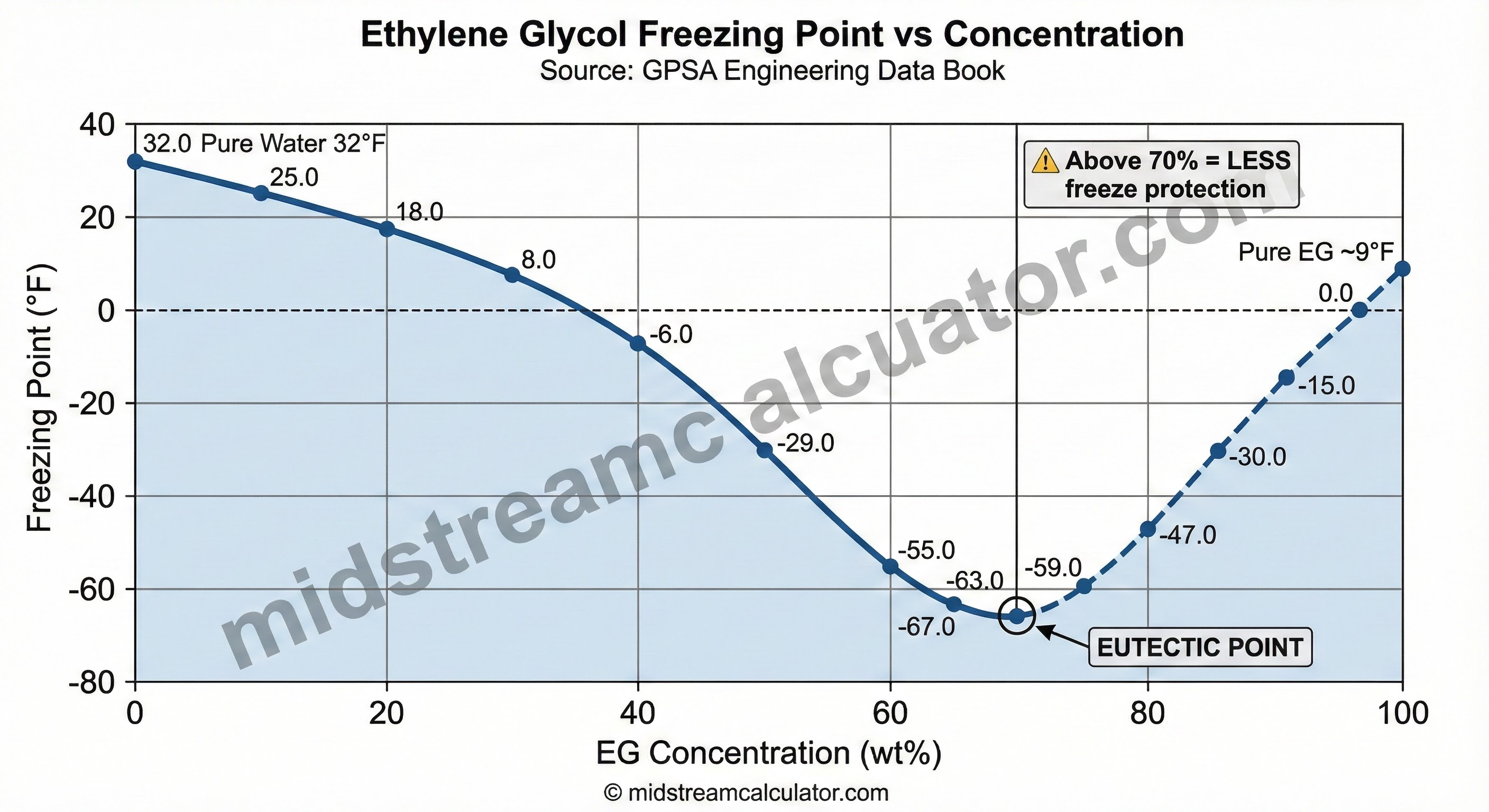
Ethylene Glycol (EG) — Freeze Protection
EG is primarily used for freeze protection in hydrate inhibition and pipeline antifreeze applications, not gas dehydration.
| Property | Value | Units | Source |
|---|---|---|---|
| Molecular Formula | C₂H₆O₂ | — | — |
| Molecular Weight | 62.1 | g/mol | GPSA Fig 6.3 |
| Density (77°F) | 9.26 | lb/gal | GPSA Fig 6.3 |
| Boiling Point (1 atm) | 387.1 | °F | GPSA Fig 6.3 |
| Freezing Point (pure) | 8 | °F | GPSA Fig 6.3 |
| Eutectic Point | ~70% / -67°F | wt% / °F | GPSA Fig 6.5 |
| Viscosity (77°F) | 16.5 | cP | GPSA Fig 6.3 |
| Thermal Decomposition | 329 | °F | GPSA Fig 6.3 |
Glycol Selection
| Application | Glycol | Why |
|---|---|---|
| Gas dehydration | TEG | Low vapor pressure, 400°F stability |
| Deep drying (<4 lb/MMscf) | TEG + stripping gas | Achieves 99.5%+ purity |
| Freeze protection | EG or MEG | Eutectic behavior, lower cost |
| Hydrate inhibition | MEG | Inject at wellhead, recover downstream |
3. Contactor Design
The contactor (absorber) brings wet gas into countercurrent contact with lean glycol. Wet gas enters the bottom; lean glycol enters the top. Water transfers from gas to glycol across the trays.
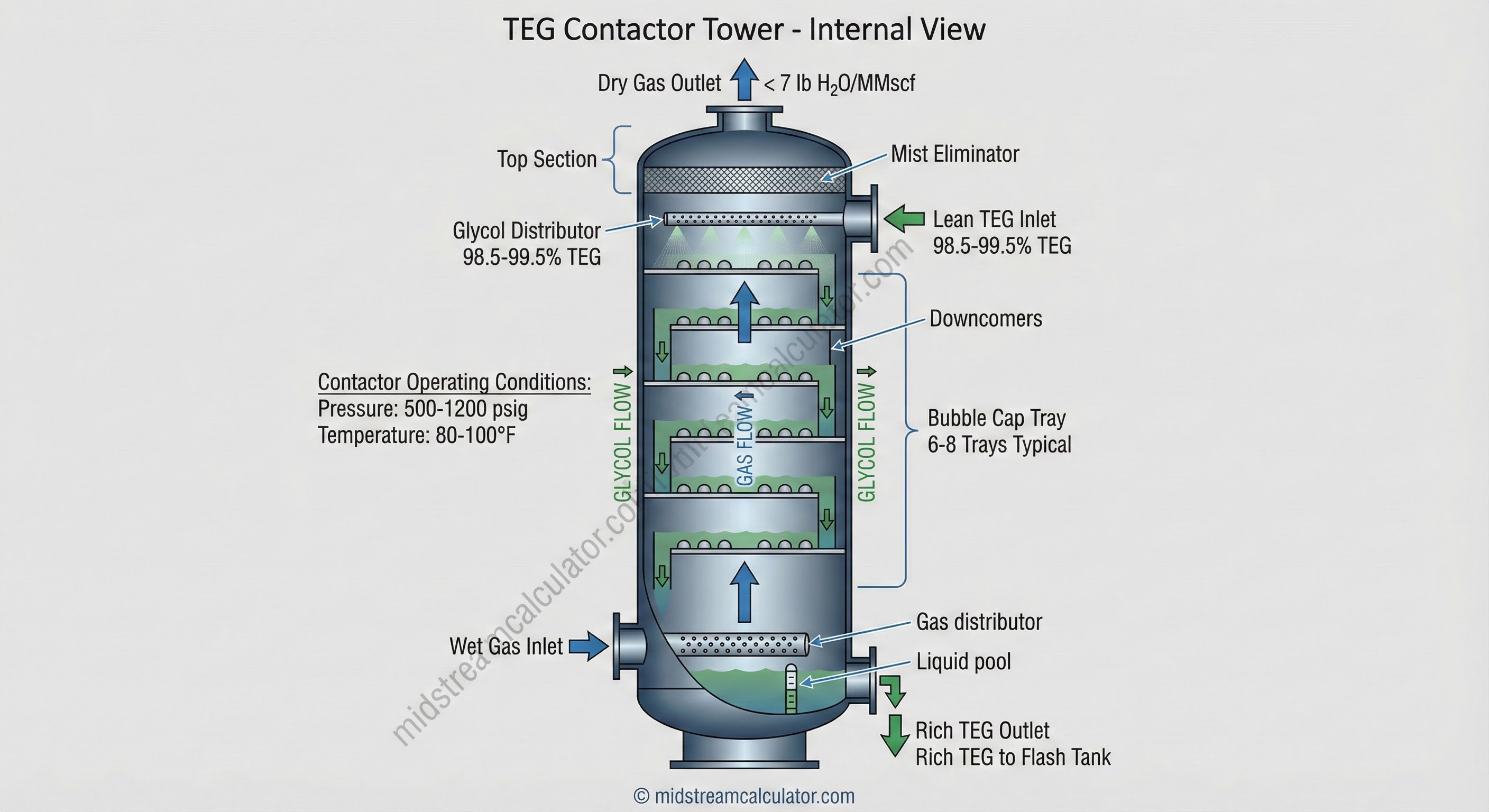
Key Design Parameters
| Parameter | Typical Value | Effect |
|---|---|---|
| Number of trays | 6–8 | More trays → deeper drying |
| Contactor temp | 80–100°F | Lower temp → better absorption |
| Contactor pressure | 500–1200 psig | Higher pressure → better removal |
| Lean TEG purity | 98.5–99.5% | Higher purity → lower outlet dew point |
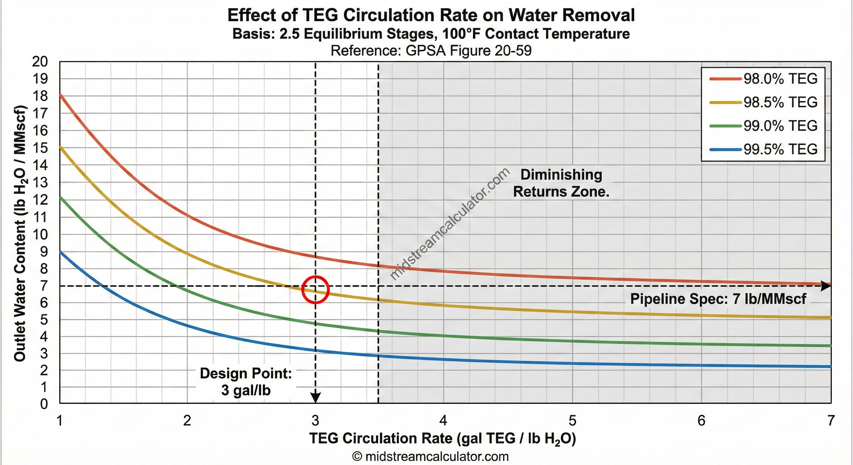
| Circulation rate | 3 gal/lb H₂O | Standard design; curves flatten here |
Temperature & Pressure Effects
4. Design Equations
Water Removal Rate
Qgas = Gas flow (MMscfd)
Win = Inlet water content (lb/MMscf)
Wout = Outlet water content (lb/MMscf)
Glycol Circulation Rate
W = Water removal (lb/hr)
G = Specific circulation = 3.0 gal TEG/lb H₂O (design standard)
Reboiler Duty — Sivalls Equation
W = Water removal (lb/hr)
G = Specific circulation (gal/lb)
At G = 3.0: Q ≈ 3,800 BTU/lb water removed
Add +10% design margin for startup loads
Example Calculation
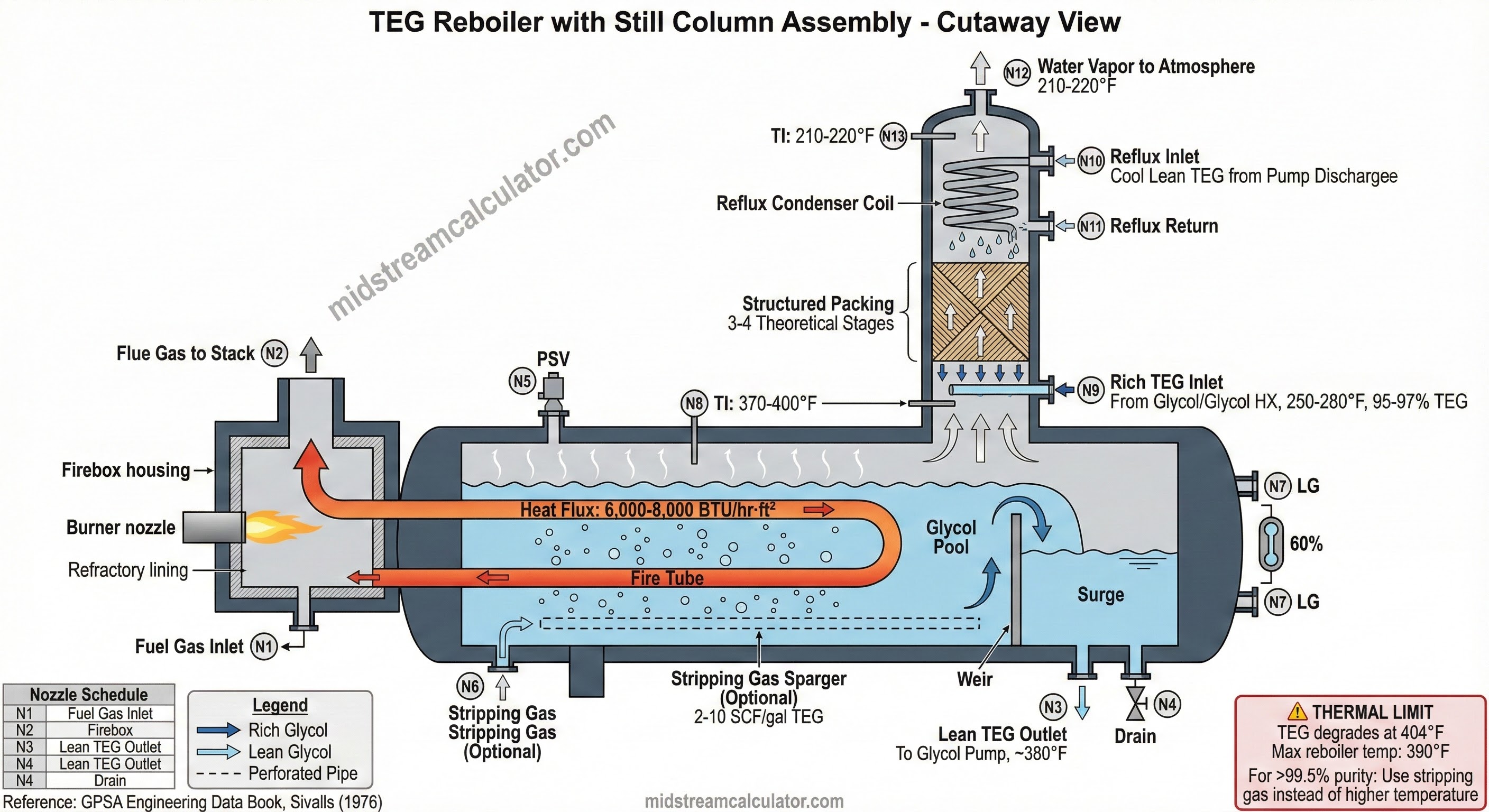
5. Regeneration System
The regenerator reconcentrates rich glycol by heating to drive off absorbed water. Reboiler temperature controls lean glycol purity.
Reboiler Temperature vs TEG Purity (Sea Level)
Source: GPSA, Figure 6.12
| TEG Purity | Reboiler Temp | Outlet Water | Notes |
|---|---|---|---|
| 96.0% | 340°F | 15–25 lb/MMscf | Minimal dehydration |
| 97.0% | 355°F | 12–15 lb/MMscf | Light-duty applications |
| 98.0% | 370°F | 7–10 lb/MMscf | Standard design point |
| 98.5% | 380°F | 5–7 lb/MMscf | Meets pipeline spec |
| 99.0% | 392°F | 4–6 lb/MMscf | Approaching thermal limit |
| 99.5% | 400°F | 2–4 lb/MMscf | At limit — use stripping gas |
| 99.9% | 404°F ⚠️ | <3 lb/MMscf | Degradation — NOT RECOMMENDED |
Enhanced Regeneration Methods
When conventional regeneration cannot achieve required TEG purity without exceeding thermal limits, use one of these enhanced methods:
| Process | TEG Purity | Dew Point Depression | Notes |
|---|---|---|---|
| Conventional | 98.5–99.0% | 60–75°F | Standard atmospheric regeneration |
| Stripping Gas | 99.2–99.9% | 100–150°F | 2–10 SCF/gal TEG; most common |
| Vacuum | 99.2–99.9% | 100–150°F | Reduces reboiler temperature |
| Coldfinger® | 99.2–99.7% | 100–130°F | Proprietary reflux process |
| Drizo® | 99.99–99.999% | 180–250°F | With solvent dryer; cryogenic prep |
Source: GPSA, Figure 6.10
Stripping Gas Details
Injecting dry gas into the reboiler/still column reduces water partial pressure, achieving higher TEG purity without exceeding safe temperatures:
- 2–5 SCF/gal: Achieves 99.5% purity at 380°F (most economical)
- 5–10 SCF/gal: Achieves 99.9% for deep drying (<3 lb/MMscf)
- >10 SCF/gal: Diminishing returns; increased TEG losses and gas consumption
Elevation Correction
At higher elevations, reduced atmospheric pressure lowers water's boiling point. The same TEG purity is achieved at ~2°F lower temperature per 1,000 ft elevation.
6. Troubleshooting Guide
| Problem | Likely Cause | Solution |
|---|---|---|
| High outlet water | Low TEG purity, insufficient circulation | Increase reboiler temp, check circulation rate |
| Dark/burnt glycol | Reboiler too hot, oxygen ingress | Lower temp to <390°F, check for air leaks |
| Foaming | Hydrocarbon contamination, solids | Check flash tank, improve filtration |
| High glycol losses | Carryover, vaporization, leaks | Check demister, lower contactor temp |
| Pump cavitation | Low surge tank level, high temp | Check level, cool glycol before pump |
TEG Loss Rates
| Mechanism | Typical Rate | Prevention |
|---|---|---|
| Vaporization | 0.01–0.05 gal/MMscf | Lower contactor temp |
| Mist carryover | 0.02–0.10 gal/MMscf | Maintain demister, limit gas velocity |
| Thermal degradation | 1–3%/year | Limit reboiler to 390°F |
Typical makeup: 5–20 gal TEG per MMscf annually. At $15–25/gal, good operation saves $500–2,000/year on a 10 MMscfd unit.
7. Glycol Care & Contamination
Proper glycol maintenance is essential for reliable dehydration performance. Contaminated glycol reduces water absorption capacity, increases losses, and can damage equipment. Understanding contamination sources enables preventive maintenance.
Seven Types of Glycol Contamination
| Contamination | Cause | Symptoms | Prevention/Treatment |
|---|---|---|---|
| 1. Oxidation | Air/oxygen exposure in surge tank or regenerator | Acidic glycol, corrosion products, dark color | Blanket surge tank with fuel gas; seal air leaks; never use air as stripping gas |
| 2. Thermal Decomposition | Reboiler temp >400°F, hot spots on fire tube | Sweet/burnt smell, dark color, reduced absorption | Limit reboiler to 390°F; maintain fire tube flux <8,000 BTU/hr/ft² |
| 3. Low pH (Acidic) | CO₂/H₂S absorption, oxidation byproducts | Corrosion, foaming, accelerated degradation | Maintain pH 7.0–7.5; add neutralizers as needed |
| 4. Salt Contamination | Produced water carryover from inlet separator | Scale deposits, pump wear, reduced efficiency | Improve inlet separation; install coalescing filter |
| 5. Hydrocarbon Contamination | Condensate carryover, flash tank malfunction | Foaming, dark viscous glycol, tray fouling | Optimize flash tank; install activated carbon filter |
| 6. Solids/Sludge | Corrosion products, pipe scale, degradation | Plugged filters, pump wear, tray fouling | Regular filtration; 5-micron sock + 10-micron cartridge |
| 7. Foaming | HC contamination, solids, low surface tension | Glycol carryover, erratic levels, poor drying | Remove root cause; antifoam as temporary fix only |
pH Control Guidelines
Filtration Requirements
- Sock filter: 5 micron — catches gross solids
- Cartridge filter: 10 micron — polishing filter
- Carbon filter: Activated carbon for HC removal
- Filter ΔP limit: Change at 15–20 psi differential
8. Visual Glycol Inspection
Regular visual inspection of glycol samples provides early warning of problems. Take samples from the surge tank or pump discharge and compare against fresh TEG.
| Appearance | Indicates | Action Required |
|---|---|---|
| Clear, light straw color | Healthy glycol | Continue normal operation |
| Dark amber to brown | Thermal degradation or oxidation | Check reboiler temp; look for air leaks |
| Black precipitate | Iron corrosion products (iron sulfide) | Check pH; investigate corrosion source |
| Black, viscous/tar-like | Heavy hydrocarbon contamination | Check flash tank; improve HC removal |
| Cloudy/milky | Water or light HC emulsion | Check regenerator operation |
| Sweet/burnt smell | Thermal decomposition | Lower reboiler temp immediately |
| Foamy when shaken | Surfactant contamination, HCs, or solids | Improve filtration; check inlet separation |
Sample Testing Frequency
| Test | Frequency | Target |
|---|---|---|
| Visual inspection | Daily | Clear, light color |
| pH measurement | Weekly | 7.0–7.5 |
| Concentration (refractometer) | Weekly | 98.5–99.5% lean |
| Full lab analysis | Monthly/Quarterly | Per vendor specs |
9. Operating Temperature Limits
Temperature control is critical throughout the glycol system. Operating outside these limits causes poor performance, equipment damage, or safety hazards.
| Location | Minimum | Maximum | Notes |
|---|---|---|---|
| Contactor | 50°F | 120°F | Below 50°F: viscosity too high; Above 120°F: poor absorption |
| Lean glycol inlet | Gas temp +10°F | — | Must be warmer than gas to prevent condensation |
| Still column | 200°F | — | Below 200°F: water won't vaporize properly |
| Reboiler (design) | 340°F | 390°F | Design max 390°F for margin below 404°F decomposition |
| Reboiler (absolute max) | — | 400°F | Never exceed; degradation begins at 404°F |
| Fire tube surface | — | ~430°F | Hot spots cause localized degradation |
| Glycol to pump | — | 200°F | Cool before pump to prevent cavitation |
Reboiler Heat Flux
Q = Burner duty (BTU/hr)
Atube = Fire tube surface area (ft²)
Higher flux = higher tube surface temp = risk of hot spots
10. Stripping Gas Operations
Stripping gas injection achieves higher TEG purity without exceeding safe reboiler temperatures. Dry gas injected into the reboiler or still column reduces water partial pressure, driving more water out of the glycol.
Stripping Gas Requirements by Purity
| Target TEG Purity | Reboiler Temp | Stripping Gas | Application |
|---|---|---|---|
| 98.3% | 350°F | 0 SCF/gal | Light duty |
| 98.7% | 375°F | 0 SCF/gal | Standard |
| 99.1% | 350°F | 0.25 SCF/gal | Enhanced at lower temp |
| 99.1% | 400°F | 0 SCF/gal | At thermal limit |
| 99.5% | 375°F | 0.20 SCF/gal | Moderate stripping |
| 99.7% | 400°F | 1 SCF/gal | Deep drying |
| 99.7% | 375°F | 2 SCF/gal | Deep drying at lower temp |
| 99.84% | 400°F | 2 SCF/gal | Very deep drying |
| 99.9% | 400°F | 3 SCF/gal | Cryogenic prep |
| 99.95% | 400°F | 6 SCF/gal | Maximum practical |
Source: Keel, L. "Glycol Dehydrators" Texas Gas Transmission, 2004
Stripping Gas Guidelines
- Gas source: Use dry sales gas or fuel gas — never air or oxygen
- Typical range: 1–6 SCF per gallon of TEG circulated
- Injection point: Into reboiler or bottom of still column
- Diminishing returns: Beyond 6 SCF/gal, benefits decrease while losses increase
- TEG losses: Stripping gas increases vaporization losses slightly
Economic Consideration
Stripping gas is consumed — it exits with water vapor through the still column. Calculate the cost of stripping gas vs. the value of deeper drying. For most pipeline applications meeting 7 lb/MMscf, stripping gas is unnecessary.
11. Startup & Shutdown Procedures
Startup Sequence
- Verify glycol inventory: Check surge tank level; add makeup TEG if needed
- Check filters: Verify filter ΔP is acceptable (<15 psi)
- Light reboiler: Start burner on low fire; bring temp up gradually over 2–4 hours
- Establish circulation: Start glycol pump once reboiler reaches 200°F
- Verify still column temp: Must reach 200°F minimum before introducing gas
- Introduce gas slowly: Open inlet valve gradually; monitor contactor level
- Adjust circulation rate: Set to design rate based on water load
- Verify outlet water content: Sample after 4–8 hours of stable operation
Normal Shutdown Sequence
- Stop gas flow: Close inlet valve; allow contactor to depressure
- Continue circulation: Run pump for 30–60 minutes to regenerate glycol
- Reduce reboiler temp: Lower to 250°F, then shut off burner
- Stop pump: Once reboiler cools below 200°F
- Blanket with fuel gas: Maintain positive pressure to prevent air ingress
- Drain if extended shutdown: For freezing conditions or >30 days
Emergency Shutdown Triggers
| Condition | Action |
|---|---|
| Reboiler temp >400°F | Shut off burner immediately |
| Surge tank low level | Stop pump to prevent cavitation |
| Fire tube glow/overheating | Emergency shutdown; inspect for fouling |
| Major glycol leak | Isolate section; maintain reboiler to prevent freezing |
| Loss of fuel gas | Controlled cooldown; maintain circulation while cooling |
Freeze Protection
TEG freezes at 19°F (pure) but concentrated TEG/water solutions may freeze at higher temperatures. For extended cold-weather shutdowns:
- Drain all low points and heat exchangers
- Leave reboiler pilot lit for warmth if possible
- Consider heat tracing on critical lines
- Never leave dilute glycol in lines during freezing weather
Related Calculators
References
- GPSA — Sections 20, 21
- Sivalls, C.R. "Glycol Dehydrator Design Manual" (1976)
- Keel, Larry P.E. "Why, How, and Operation of Glycol Dehydrators" — Texas Gas Transmission, LLC (2004)
- API 12GDU — Specification for Glycol-Type Gas Dehydration Units
- Campbell, J.M. "Gas Conditioning and Processing", Vol. 2
Ready to use the calculator?
→ Launch Calculator