1. Cylinder Stress Theory
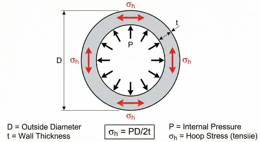
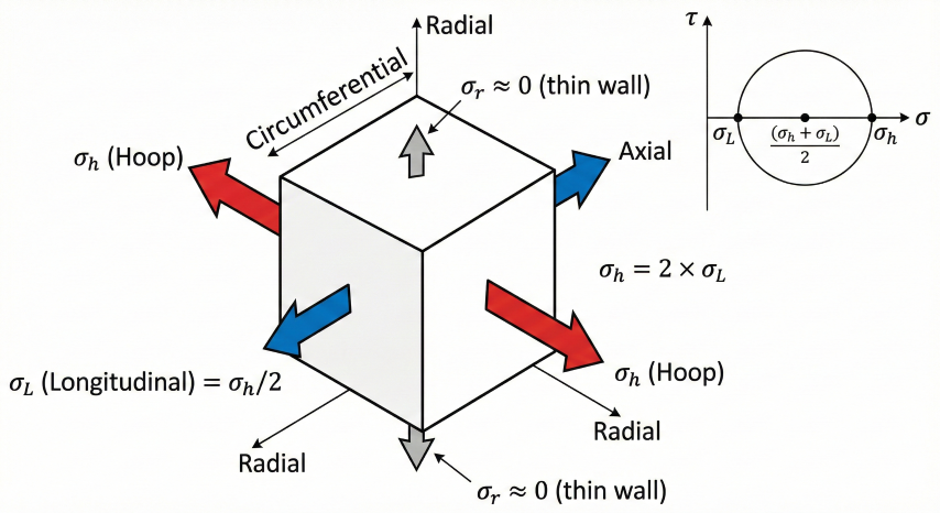
When a pipe is pressurized internally, stress develops in the pipe wall in three directions: circumferential (hoop), longitudinal (axial), and radial. For thin-walled pipes, hoop stress dominates and is the basis for pressure design.
Thin-Wall Assumption
Barlow's formula assumes uniform stress distribution through the wall thickness. This is valid when:
- D/t > 20: Stress varies less than 5% through wall
- D/t > 10: Acceptable for design (error < 10%)
- D/t < 10: Use Lamé equations for thick-wall analysis
Principal Stresses in Pressurized Cylinders
| Stress Component | Formula (Thin-Wall) | Ratio to σh |
|---|---|---|
| Hoop (circumferential) | σh = PD / 2t | 1.00 |
| Longitudinal (axial) | σL = PD / 4t | 0.50 |
| Radial | σr ≈ −P (ID) to 0 (OD) | ≈ 0 (thin-wall) |
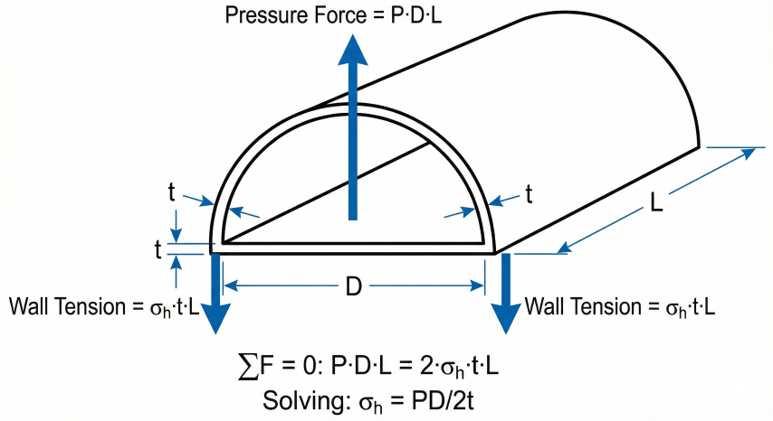
2. Barlow's Formula
Peter Barlow published this formula in 1836 for calculating stress in cylindrical pressure vessels. It remains the fundamental equation for pipeline design.
Rearranged Forms
| Solve For | Formula | Application |
|---|---|---|
| Wall thickness | t = PD / (2S) | Minimum wall for given pressure |
| Pressure (MAOP) | P = 2St / D | Maximum allowable pressure |
| Stress | S = PD / 2t | Verify existing pipe |
OD vs. Mean Diameter
The regulatory formula (49 CFR 192.105) uses outside diameter, which yields a conservative (higher) stress. For more accurate stress analysis:
Example Calculation
Given: 16" OD × 0.375" wall, 1000 psig, X52 pipe
S = (1000 × 16) / (2 × 0.375)
S = 16,000 / 0.75
S = 21,333 psi (41% of 52,000 SMYS)
3. ASME B31.8 Design Factors
Pipeline codes limit allowable stress to a fraction of the pipe's Specified Minimum Yield Strength (SMYS). The complete design equation includes multiple factors:
Design Factor (F) by Location Class
| Class | F | %SMYS | Description |
|---|---|---|---|
| 1 | 0.72 | 72% | Rural (≤10 buildings/mile) |
| 2 | 0.60 | 60% | Fringe (11–46 buildings) |
| 3 | 0.50 | 50% | Suburban (≥46 buildings) |
| 4 | 0.40 | 40% | Urban (multi-story prevalent) |
Joint Factor (E) per ASME B31.8 Table 841.1.7-1
| Pipe Type | E Factor |
|---|---|
| Seamless | 1.00 |
| ERW/EFW (post-1970) | 1.00 |
| ERW (1960–1970) | 0.85 |
| ERW/Flash Weld (pre-1960) | 0.80 |
| Spiral Weld | 0.80–1.00 |
| Furnace Butt Weld | 0.60 |
Temperature Derating (T) per Table 841.1.8-1
| Temperature (°F) | T Factor |
|---|---|
| ≤ 250 | 1.000 |
| 300 | 0.967 |
| 350 | 0.933 |
| 400 | 0.900 |
| 450 | 0.867 |
Common SMYS Values (API 5L)
| Grade | SMYS (psi) | SMYS (MPa) |
|---|---|---|
| B | 35,000 | 245 |
| X42 | 42,000 | 290 |
| X52 | 52,000 | 360 |
| X60 | 60,000 | 415 |
| X65 | 65,000 | 450 |
| X70 | 70,000 | 485 |
| X80 | 80,000 | 555 |
4. ASME B31.3 Process Piping
ASME B31.3 governs process piping in refineries, chemical plants, and gas processing facilities. Unlike B31.8's location-based design factors, B31.3 uses allowable stress values derived from material properties with safety factors applied.
Wall Thickness Formula
B31.3 uses a modified Barlow's formula that accounts for internal pressure's contribution to stress:
Y Coefficient (Table 304.1.1)
The Y coefficient accounts for stress redistribution in the pipe wall under pressure. It varies with temperature and material type:
| Material | ≤900°F | 950°F | 1000°F | ≥1050°F |
|---|---|---|---|---|
| Ferritic steels | 0.4 | 0.5 | 0.7 | 0.7 |
| Austenitic steels | 0.4 | 0.4 | 0.4 | 0.4 |
| Nickel alloys | 0.4 | 0.4 | 0.4 | 0.4 |
Simplified: For temperatures ≤900°F and D/t > 6, Y = 0.4 is commonly used.
Allowable Stress (S)
B31.3 allowable stress is the lower of:
- SMYS / 3.0 (yield-based)
- SMTS / 3.0 (tensile-based)
- Stress-rupture at temperature (creep range)
Weld Joint Quality Factor (E)
Per B31.3 Table A-1B:
| Joint Type | E Factor |
|---|---|
| Seamless pipe | 1.00 |
| ERW (ASTM A53 Type E) | 1.00 |
| Furnace butt weld (ASTM A53 Type F) | 0.60 |
| Electric fusion weld (double) | 1.00 |
| Electric fusion weld (single) | 0.80 |
| API 5L (ERW, SMLS, DSAW) | 1.00 |
MAWP Calculation
Maximum Allowable Working Pressure for existing pipe:
Example: B31.3 vs B31.8
Given: 8" Sch 40 (OD=8.625", t=0.322"), 52,000 psi SMYS, 100°F
B31.8 (Class 1):
P = 2 × 52,000 × 0.322 × 0.72 / 8.625
P = 2,794 psig
B31.3:
S = 52,000 / 3 = 17,333 psi
P = 2 × 17,333 × 1.0 × 0.322 / (8.625 - 2×0.4×0.322)
P = 11,162 / 8.367 = 1,334 psig
B31.3 yields ~48% of B31.8 allowable pressure due to more conservative safety factors.
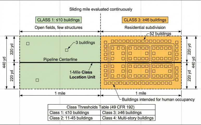
5. Location Classification
Location class determines the design factor and is based on building density along the pipeline corridor. Per 49 CFR 192.5:
Class Definitions
- Class 1: ≤10 buildings intended for human occupancy within the 1-mile × 440-yard sliding rectangle
- Class 2: 11–46 buildings, or an area where development is likely
- Class 3: ≥46 buildings, or within 100 yards of a building with 20+ occupants (schools, churches, hospitals)
- Class 4: Areas where 4+ story buildings are prevalent
6. Design Applications
New Pipeline Design
Select wall thickness for design pressure and location class:
Problem: Select wall for 24" pipeline, 1200 psig MAOP, Class 1, X65 pipe
Given: D = 24", P = 1200 psig, S = 65,000 psi, F = 0.72, E = 1.0, T = 1.0
t = PD / (2 × S × F × E × T)
t = (1200 × 24) / (2 × 65,000 × 0.72 × 1.0 × 1.0)
t = 28,800 / 93,600
t = 0.308" → Select 0.344" (STD) or 0.375"
Manufacturing Tolerance
API 5L PSL2 allows negative tolerance on wall thickness:
- t ≤ 0.197" (5 mm): −12.5%
- t > 0.197": −10% (min 0.5 mm)
For stress verification of existing pipe, use minimum wall (nominal × 0.875 or 0.90).
Von Mises Equivalent Stress
For combined stress analysis (ductile materials):
7. Code Requirements
Applicable Codes & Regulations
| Code | Application | Jurisdiction |
|---|---|---|
| 49 CFR Part 192 | Gas transmission & distribution | DOT/PHMSA (Federal) |
| 49 CFR Part 195 | Hazardous liquids | DOT/PHMSA (Federal) |
| ASME B31.8 | Gas transmission design | Industry (referenced) |
| ASME B31.3 | Process piping (plants) | Industry standard |
| ASME B31.4 | Liquid petroleum | Industry (referenced) |
| API 5L | Line pipe specification | Industry standard |
Regulatory Hierarchy: 49 CFR 192/195 are federal regulations (mandatory). ASME B31.8/B31.4 are industry codes referenced by regulations. When conflicts exist, federal regulations take precedence.
Hydrostatic Testing (49 CFR 192.505)
| Location Class | Minimum Test Pressure | Duration |
|---|---|---|
| Class 1 | 1.25 × MAOP | 8 hours |
| Class 2 | 1.25 × MAOP | 8 hours |
| Class 3 | 1.40 × MAOP | 8 hours |
| Class 4 | 1.40 × MAOP | 8 hours |
Industry Practice: 1.5× MAOP is common for new construction to establish MAOP margin.
Key Design Requirements
- Maximum stress: 72% SMYS for Class 1 gas transmission
- Manufacturing tolerance: Account for −12.5% wall per API 5L
- Corrosion allowance: Add to minimum calculated thickness
- Pressure surge: May require additional wall for water hammer
References
- 49 CFR Part 192 – Transportation of Natural Gas by Pipeline (DOT/PHMSA)
- 49 CFR Part 195 – Transportation of Hazardous Liquids by Pipeline
- ASME B31.8-2022 – Gas Transmission and Distribution Piping Systems
- ASME B31.3-2022 – Process Piping
- ASME B31.4-2022 – Pipeline Transportation Systems for Liquids
- API 5L (46th Edition) – Specification for Line Pipe
- ASME B31G – Manual for Determining Remaining Strength of Corroded Pipelines
Ready to use the calculator?
→ Launch Calculator