Material Behavior

Thermal Expansion Calculations

Calculate linear and volumetric thermal expansion for pipelines, tanks, and equipment using expansion coefficients and stress analysis per ASME B31.3/B31.8.

Carbon Steel

6.5×10⁻⁶ /°F

0.78" per 100 ft per 100°F rise

Thermal Stress

188 psi/°F

Fully restrained carbon steel (E×α)

Liquid Expansion

0.04-0.07%/°F

Petroleum products volume change

Use this guide when:

  • Calculating pipeline expansion and loop sizing
  • Analyzing thermal stresses in constrained piping
  • Determining tank freeboard for liquid expansion

1. Overview

Thermal expansion is the tendency of materials to change dimensions in response to temperature changes. In pipeline and process systems, unaccommodated thermal expansion causes equipment damage, flange leaks, and pipe buckling.

Pipelines

Expansion Loops

Above-ground and buried lines require expansion accommodation to prevent overstress.

Storage Tanks

Freeboard

API 650 requires freeboard to prevent overfill from liquid expansion.

Piping Systems

Flexibility Analysis

ASME B31.3 requires thermal stress analysis for process piping.

Equipment

Thermal Relief

Blocked-in equipment requires PSV sizing for thermal expansion.

Key Definitions

  • Linear expansion coefficient (α): Length change per unit length per degree (in/in/°F)
  • Volumetric expansion coefficient (β): Volume change per unit volume per degree (β ≈ 3α for solids)
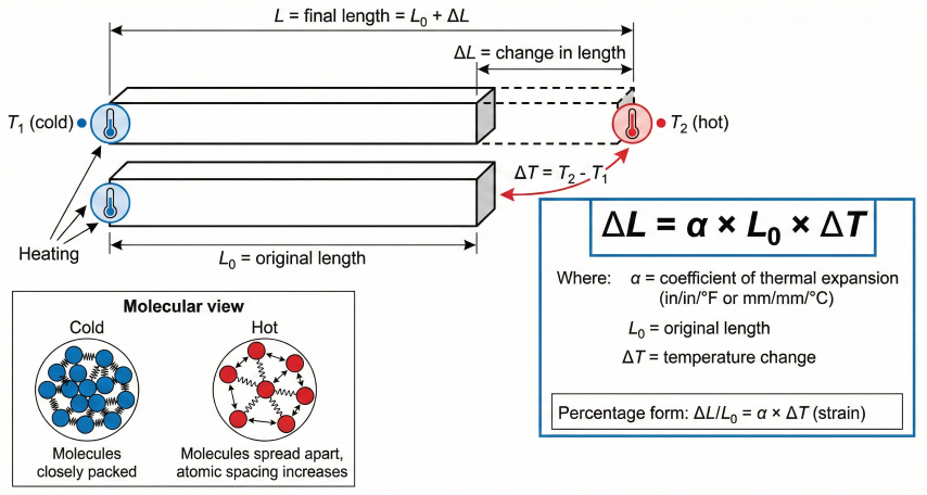
  • Thermal strain: ε = α × ΔT (dimensionless)
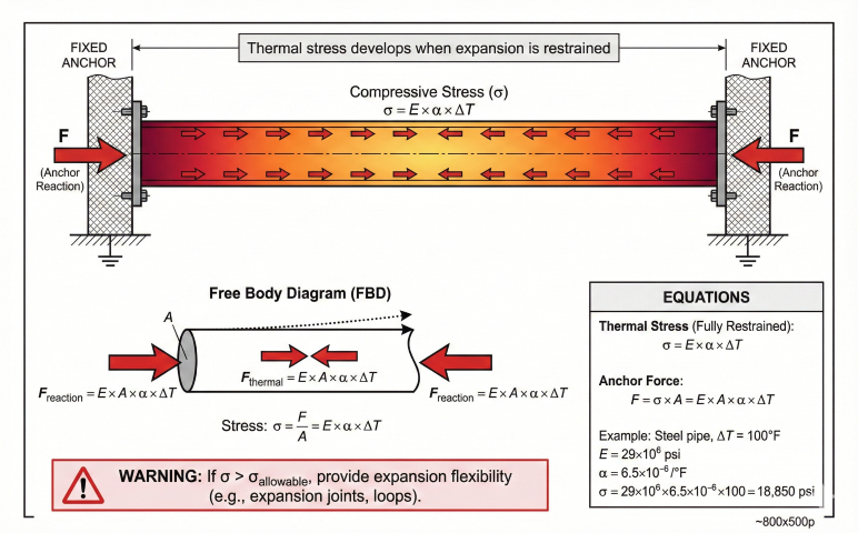
  • Thermal stress: σ = E × α × ΔT (stress when expansion is restrained)
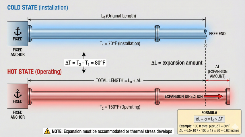
Why it matters: A 1000-ft carbon steel pipeline exposed to 100°F temperature change expands 7.8 inches. Without proper accommodation, this generates ~165 tons of force at anchors, enough to damage equipment or cause pipe buckling.
Pipeline thermal expansion showing cold state at installation temperature 70°F and hot operating state at 150°F with expansion amount ΔL labeled and formula
Thermal expansion: Steel pipeline expands ~0.62 inches per 100 ft for 80°F temperature rise; must be accommodated or stress develops.

2. Linear Expansion

Linear thermal expansion describes length change with temperature. This is the primary concern for pipeline design and piping flexibility.

Linear Expansion Equation: ΔL = α × L₀ × ΔT Where: ΔL = Change in length (inches) α = Linear expansion coefficient (in/in/°F) L₀ = Original length at reference temperature (inches) ΔT = Temperature change (°F) Final length: L = L₀ × (1 + α × ΔT)

Calculation Example

Calculate expansion of 500-ft carbon steel pipeline with 150°F temperature increase:

Given: L₀ = 500 ft = 6,000 inches α = 6.5×10⁻⁶ in/in/°F ΔT = 150°F Solution: ΔL = 6.5×10⁻⁶ × 6,000 × 150 ΔL = 5.85 inches Rule of thumb check: 0.78 in/100ft/100°F × (500/100) × (150/100) = 5.85 in ✓
Bar diagram showing linear thermal expansion with original length L₀, change in length ΔL, temperature change ΔT, molecular view inset, and formula ΔL = α × L₀ × ΔT
Linear expansion equation: ΔL = α × L₀ × ΔT; molecular spacing increases with temperature causing macroscopic length change.

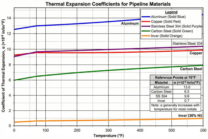
3. Expansion Coefficients

Expansion coefficients vary by material and temperature. Use mean coefficient over the operating temperature range for accurate calculations.

Common Piping Materials

Material α (×10⁻⁶ /°F) Expansion per 100 ft per 100°F E (×10⁶ psi)
Carbon Steel (A106) 6.5 0.78 in 29.0
Stainless Steel 304 9.6 1.15 in 28.3
Stainless Steel 316 9.0 1.08 in 28.0
9% Nickel (A353) 7.0 0.84 in 28.5
Aluminum 6061 13.0 1.56 in 10.0
Copper 9.8 1.18 in 17.0
PVC 30.0 3.60 in 0.4
HDPE 80.0 9.60 in 0.11

Temperature-Dependent Coefficients (Carbon Steel)

For wide temperature ranges, use mean coefficient from ASME B31.3 Appendix C:

Temperature Range (°F) Mean α (×10⁻⁶ /°F) Application
-20 to 200 6.3 Typical gas pipelines
70 to 300 6.5 Standard process piping
70 to 500 6.7 Heated oil lines
70 to 700 7.0 High-temp process
70 to 900 7.3 Furnace piping, flares
Chart showing thermal expansion coefficients versus temperature for aluminum, copper, stainless steel 304, carbon steel, and Invar alloy from 0 to 600°F
Expansion coefficients: Aluminum highest (~13×10⁻⁶), carbon steel mid-range (~6.5×10⁻⁶), Invar extremely low (~0.7×10⁻⁶) for precision applications.

4. Thermal Stress Analysis

When thermal expansion is restrained, stresses develop. ASME B31 piping codes require flexibility analysis to ensure thermal stresses remain within allowable limits.

Thermal Stress (Fully Restrained): σ = E × α × ΔT For carbon steel: σ = 29×10⁶ × 6.5×10⁻⁶ × ΔT σ = 188.5 × ΔT (psi per °F) Example: ΔT = 200°F σ = 188.5 × 200 = 37,700 psi This exceeds yield strength of most steels! Piping must be designed for flexibility.

Allowable Stress Range (ASME B31.3)

Expansion Stress Range: S_A = f × (1.25 S_c + 0.25 S_h) Where: S_A = Allowable stress range (psi) S_c = Cold allowable stress S_h = Hot allowable stress f = Stress range factor (1.0 for N ≤ 7,000 cycles) For carbon steel (S_c = S_h = 20,000 psi): S_A = 1.0 × (1.25 × 20,000 + 0.25 × 20,000) S_A = 30,000 psi (for limited cycles) Expansion stress is self-limiting—yields locally and redistributes ("shakes down" to elastic behavior).

Anchor Force Calculation

Anchor Force (Fully Restrained): F = E × A × α × ΔT Where: F = Anchor force (lbs) A = Pipe wall cross-sectional area (in²) Example: 12" Sch Std pipe, ΔT = 120°F A = 14.58 in² (pipe wall area) F = 29×10⁶ × 14.58 × 6.5×10⁻⁶ × 120 F = 330,000 lbs (165 tons!) Anchors must be designed for these massive forces.
Fully restrained pipe showing compressive thermal stress σ=E×α×ΔT, anchor reaction forces F at both ends, free body diagram, and example calculation showing 18,850 psi for 100°F rise
Thermal stress in restrained pipe: σ = E×α×ΔT develops when expansion is prevented; provide flexibility if stress exceeds allowable.

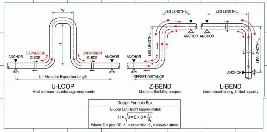
5. Expansion Loops & Flexibility

Expansion must be accommodated through piping flexibility, expansion loops, or mechanical expansion joints.

Expansion Loop Sizing

U-Loop Leg Height (Approximate): H ≈ √(D × ΔL / 6) Where: H = Loop leg height (ft) D = Pipe OD (inches) ΔL = Expansion to absorb (inches) Example: 12" pipe, ΔL = 6 inches H = √(12.75 × 6 / 6) = √12.75 = 3.6 ft Use minimum 4 ft for practical construction. For accurate design, use CAESAR II or AutoPIPE.

Expansion Accommodation Methods

Method Advantages Limitations
Natural flexibility (elbows) No additional equipment; lowest cost Requires sufficient routing flexibility
Expansion loops (U/Z shape) Reliable; no moving parts; no maintenance Requires space; adds pressure drop
Bellows expansion joints Compact; high movement capacity Requires anchors; limited life; maintenance
Ball joints Handles large angular rotation Expensive; limited pressure rating
Three expansion loop configurations: U-loop for large movements, Z-bend for moderate flexibility in compact space, and L-bend using natural routing with limited capacity
Expansion flexibility: U-loop absorbs large movements; Z-bend for moderate offset; L-bend uses natural direction changes.

Support Types

Support Type Function Thermal Consideration
Anchor Prevents all movement Absorbs full thermal force—must be designed for high loads
Guide Allows axial movement Clearance must accommodate full expansion
Slide support Allows lateral movement Friction force = μ × Weight (μ ≈ 0.3 for PTFE)
Spring hanger Supports weight with movement Select spring range for thermal displacement
Installation tip: Install above-ground pipelines at mid-range temperature when possible. If operating range is 20-120°F, install at 70°F to minimize anchor loads in both directions.

6. Volumetric Expansion

Volumetric expansion is critical for liquid storage tanks, custody transfer calculations, and thermal relief valve sizing.

Volumetric Expansion: ΔV = β × V₀ × ΔT Where: ΔV = Volume change (gallons) β = Volumetric coefficient (1/°F) V₀ = Original volume (gallons) ΔT = Temperature change (°F) For solids: β ≈ 3α For liquids: β measured experimentally (varies with temperature)

Liquid Expansion Coefficients

Fluid β (×10⁻⁴ /°F) Volume Change per 10°F
Water (60°F) 1.1 0.11%
Crude oil (API 30) 4.0 0.40%
Gasoline 6.8 0.68%
Diesel fuel 5.0 0.50%
Propane (liquid) 9.8 0.98%

Tank Freeboard Calculation

API 650 Freeboard: Required freeboard = ΔV / A_tank + safety margin Example: 80-ft diameter tank, 30-ft liquid level, crude oil Tank area: A = π × (40)² = 5,027 ft² Volume: V = 5,027 × 30 = 150,810 ft³ β = 4.0×10⁻⁴ /°F, ΔT = 40°F (summer heating) ΔV = 150,810 × 4.0×10⁻⁴ × 40 = 2,413 ft³ Height rise = 2,413 / 5,027 = 0.48 ft = 5.8 in With 18" safety margin: Required freeboard = 5.8 + 18 = 24 inches minimum

Custody Transfer Impact

Volume measurement errors from temperature have significant financial impact:

Example: 50,000 bbl/day crude, $70/bbl Temperature error: 5°F β ≈ 4.0×10⁻⁴ /°F Volume error = 50,000 × 4.0×10⁻⁴ × 5 = 100 bbl/day Revenue error = 100 × $70 = $7,000/day Annual impact = $2.55 million/year ASTM D1250 requires ±0.5°F accuracy for custody transfer.
API volume correction: Petroleum products are measured at actual temperature but reported at standard 60°F using ASTM D1250 correction tables. Hot product occupies more volume but corrects to smaller volume at 60°F.