1. Beam Theory Basics
When a pipe spans between supports, it acts as a beam carrying its own weight plus any additional loads. The Euler-Bernoulli beam theory relates bending moment to stress through the flexure formula.
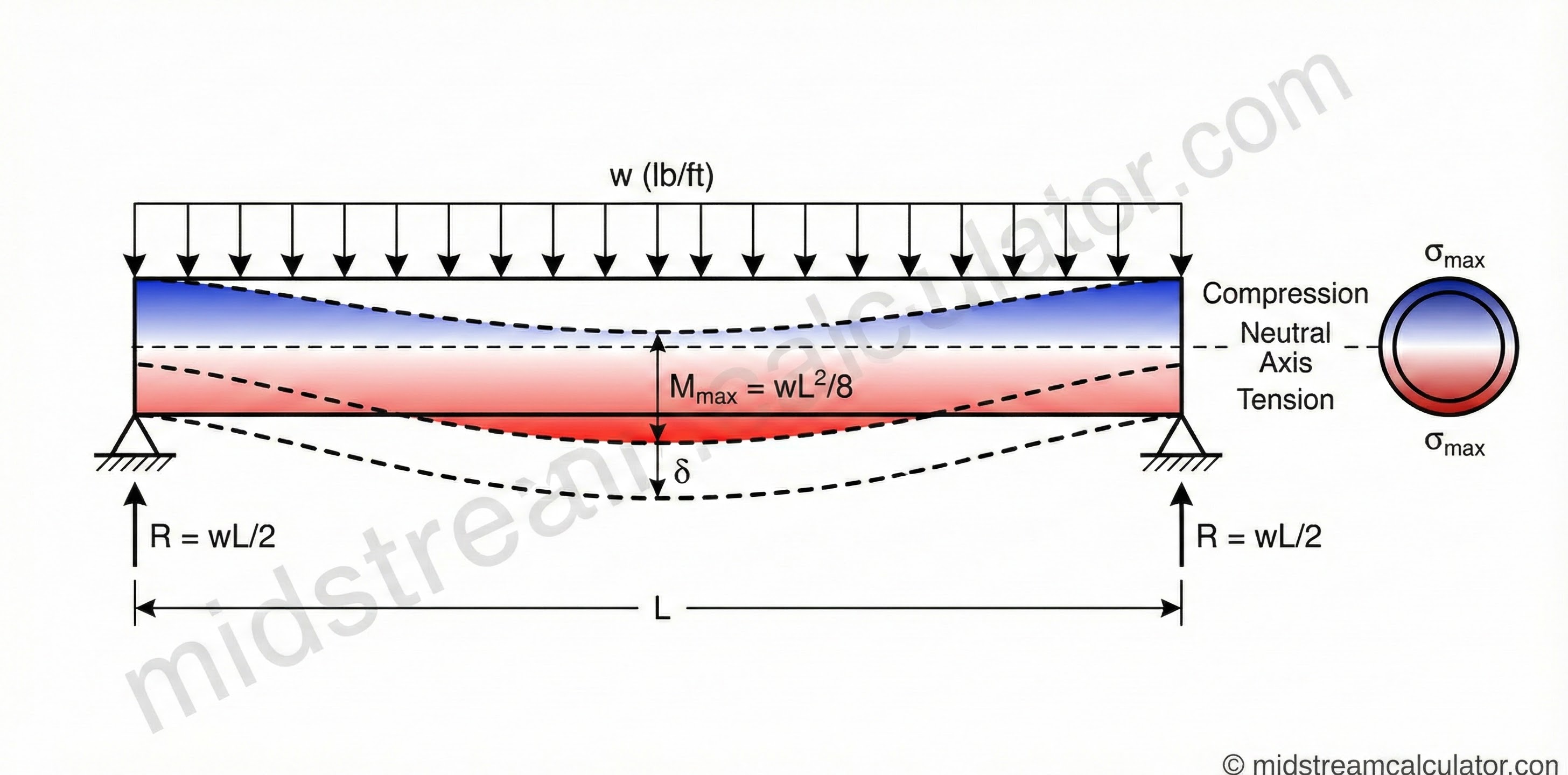
The maximum bending stress occurs at the outer fiber of the pipe cross-section. For hollow circular sections (pipes), the stress distribution is linear from zero at the neutral axis to maximum at the outer surface.
Support Configurations
The support type significantly affects both stress and deflection. Common configurations for pipeline spans:
Simply Supported
Pinned-Pinned
Both ends free to rotate. Mmax = wL²/8 at midspan.
Fixed-Pinned
Propped Cantilever
One end fixed, one pinned. Mmax = wL²/8 at fixed end.
Fixed-Fixed
Both Ends Fixed
Lowest deflection. Mmax = wL²/12 at supports.
Cantilever
Fixed-Free
Highest stress. Mmax = wL²/2 at fixed end.
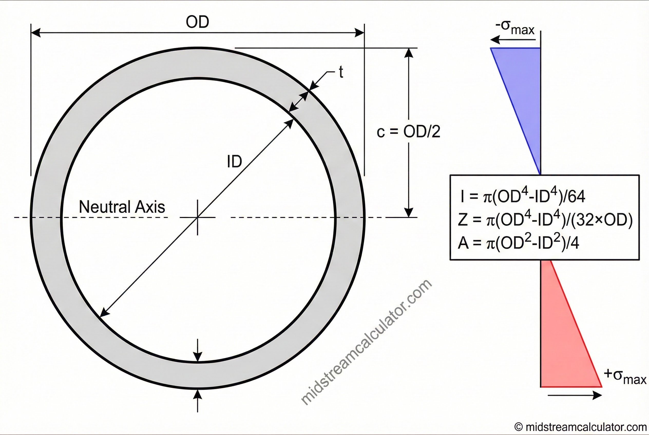
2. Pipe Section Properties
The geometric properties of the pipe cross-section determine its resistance to bending. For a hollow circular section:
Common Pipe Properties (Schedule 40)
| NPS | OD (in) | Wall (in) | Wt (lb/ft) | I (in⁴) | Z (in³) |
|---|---|---|---|---|---|
| 4 | 4.500 | 0.237 | 10.79 | 7.23 | 3.21 |
| 6 | 6.625 | 0.280 | 18.97 | 28.14 | 8.50 |
| 8 | 8.625 | 0.322 | 28.55 | 72.49 | 16.81 |
| 10 | 10.750 | 0.365 | 40.48 | 160.8 | 29.9 |
| 12 | 12.750 | 0.375 | 49.56 | 279.3 | 43.8 |
| 16 | 16.000 | 0.375 | 62.58 | 560.7 | 70.1 |
| 20 | 20.000 | 0.375 | 78.60 | 1,113 | 111.3 |
| 24 | 24.000 | 0.375 | 94.62 | 1,943 | 162 |
Pipe Weight Calculation
3. Deflection Formulas
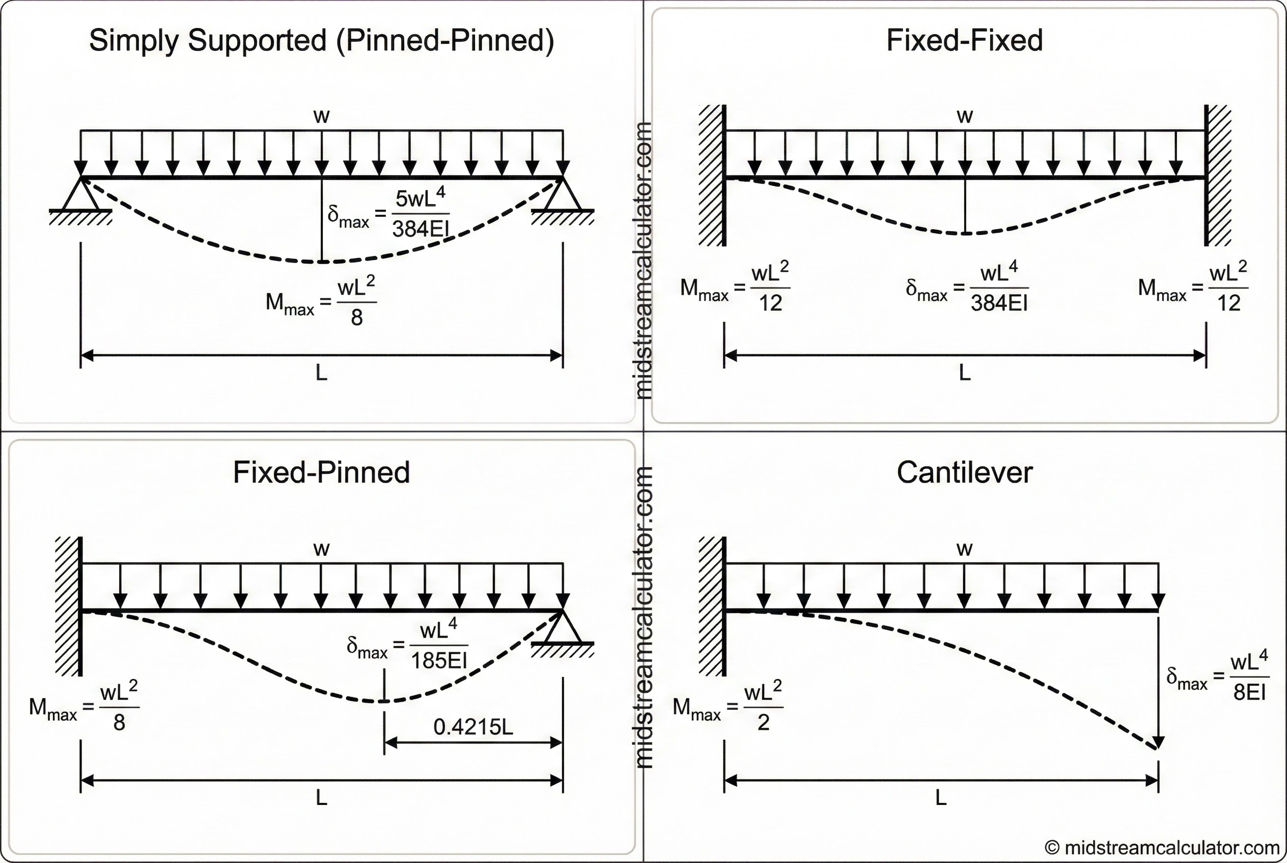
Deflection must be checked to ensure the pipe does not sag excessively. The formulas below are for uniform distributed load w over span L.
| Support Type | Max Moment | Max Deflection | Location of δmax |
|---|---|---|---|
| Simply Supported | wL²/8 | 5wL⁴/(384EI) | Midspan (L/2) |
| Fixed-Fixed | wL²/12 | wL⁴/(384EI) | Midspan (L/2) |
| Fixed-Pinned | wL²/8 | wL⁴/(185EI) | 0.4215L from pinned end |
| Cantilever | wL²/2 | wL⁴/(8EI) | Free end |
Relative Deflection Comparison
Taking simply supported as baseline (1.0):
| Support Type | Relative Moment | Relative Deflection |
|---|---|---|
| Simply Supported | 1.00 | 1.00 |
| Fixed-Fixed | 0.67 | 0.20 |
| Fixed-Pinned | 1.00 | 0.42 |
| Cantilever | 4.00 | 9.60 |
4. ASME B31.8 Stress Criteria
ASME B31.8 distinguishes between restrained (buried) and unrestrained (above-ground) piping. Above-ground spans are typically unrestrained, governed by §833.6.
Unrestrained Pipe (§833.6)
Design Factors (Table 841.1.6-1)
| Location Class | Design Factor (F) | Description |
|---|---|---|
| Class 1, Div 1 | 0.72 | Sparsely populated, no buildings |
| Class 1, Div 2 | 0.60 | Offshore, platform gathering |
| Class 2 | 0.60 | Fringe areas, 11-45 buildings |
| Class 3 | 0.50 | Suburban, 46+ buildings |
| Class 4 | 0.40 | 4+ story buildings common |
Temperature Derating (Table 841.1.8-1)
| Temperature (°F) | Derating Factor (T) |
|---|---|
| ≤ 250 | 1.000 |
| 300 | 0.967 |
| 350 | 0.933 |
| 400 | 0.900 |
| 450 | 0.867 |
Joint Factors (Table 841.1.7-1)
| Pipe Type | Joint Factor (E) |
|---|---|
| Seamless | 1.00 |
| ERW (Electric Resistance Welded) | 1.00 |
| Submerged Arc Welded (SAW) | 1.00 |
| Furnace Butt Welded | 0.60 |
5. Design Practice
Maximum Span Calculation
Rearranging the bending stress equation to solve for allowable span:
Typical Support Spacing Guidelines
| NPS | Gas (Empty) | Liquid (Full) | Hydrotest |
|---|---|---|---|
| 4–6 | 18–22 ft | 14–18 ft | 12–15 ft |
| 8–10 | 22–28 ft | 18–22 ft | 15–18 ft |
| 12–16 | 28–35 ft | 22–28 ft | 18–22 ft |
| 20–24 | 35–42 ft | 28–35 ft | 22–28 ft |
Design Considerations
Thermal Expansion: Above-ground pipelines expand/contract with temperature changes. Provide at least one sliding support per span to accommodate axial movement. Fixed supports at both ends create high thermal stress.
Hydrotest Conditions: Water-filled lines weigh significantly more than gas-filled. Always check span adequacy for hydrotest. Water adds approximately:
- 4" pipe: +5.5 lb/ft
- 8" pipe: +20 lb/ft
- 12" pipe: +45 lb/ft
- 24" pipe: +180 lb/ft
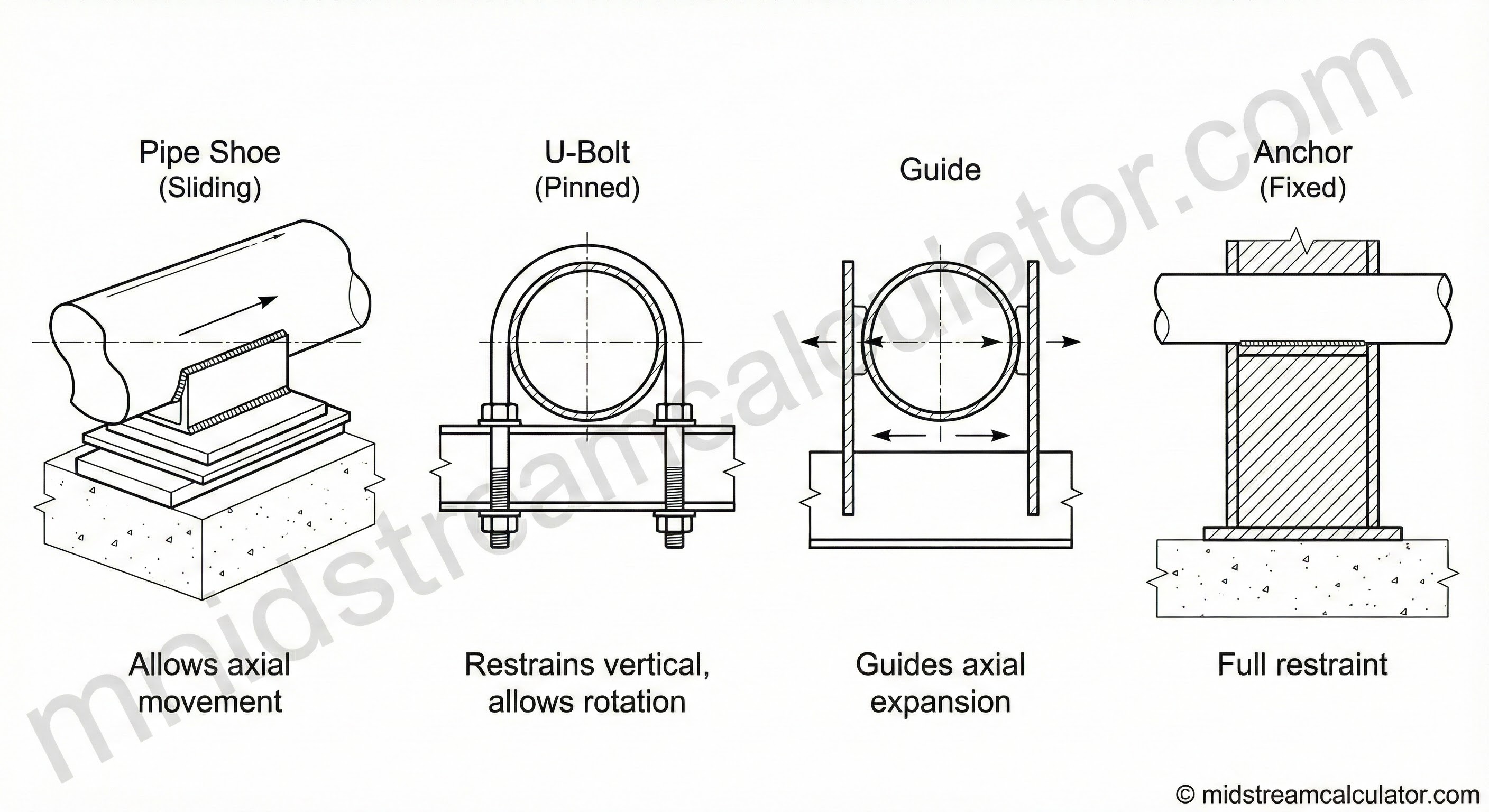
Support Types:
- Pipe shoes: Welded saddles, high capacity, allows sliding
- U-bolts: Simple, adjustable, lower capacity
- Roller supports: For thermal expansion accommodation
- Guides: Restrain lateral movement, allow axial
Common Mistakes to Avoid
- Ignoring fluid weight during hydrotest
- Assuming fixed supports without designing moment connections
- Not checking deflection (sag can cause drainage issues)
- Over-restraining thermal expansion
- Using wrong section modulus (Z, not plastic modulus Zp)
Ready to use the calculator?
→ Launch Calculator