1. SMYS Definition
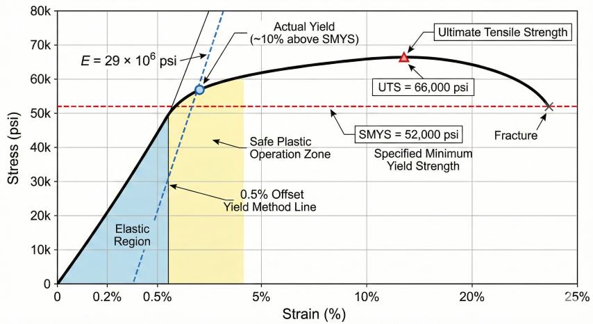
Specified Minimum Yield Strength (SMYS) is the minimum yield strength guaranteed by the pipe manufacturer per API 5L or ASTM specifications. It represents the stress at which the material transitions from elastic to plastic deformation—the threshold where permanent deformation begins.
Key Concepts
- Yield strength: Stress at 0.5% total elongation (API 5L) or 0.2% offset (ASTM)
- SMYS: Minimum guaranteed value—actual yield is typically 5–15% higher
- Ultimate tensile strength (UTS): Maximum stress before fracture, always exceeds yield
- Elastic modulus: 29 × 10⁶ psi for carbon steel (slope of elastic region)
API 5L Pipe Grade Properties
| Grade | SMYS (psi) | SMYS (MPa) | Min UTS (psi) | Typical Use |
|---|---|---|---|---|
| Grade B | 35,000 | 241 | 60,000 | Low-pressure gathering |
| X42 | 42,000 | 290 | 60,000 | Distribution systems |
| X52 | 52,000 | 359 | 66,000 | Standard transmission |
| X60 | 60,000 | 414 | 75,000 | Higher-pressure transmission |
| X65 | 65,000 | 448 | 77,000 | High-pressure transmission |
| X70 | 70,000 | 483 | 82,000 | Long-distance pipelines |
| X80 | 80,000 | 552 | 90,000 | Offshore/high-stress |
2. Stress Calculations
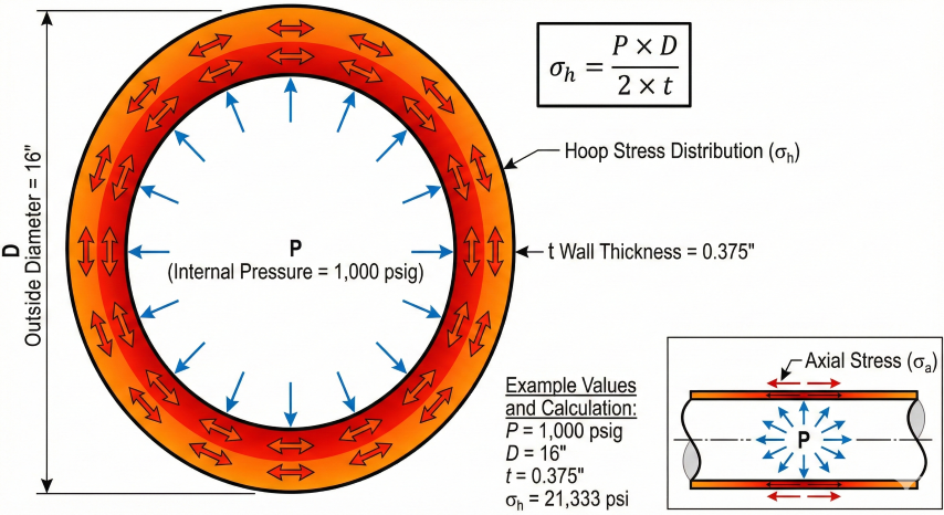
Hoop Stress (Barlow's Formula)
Internal pressure creates circumferential (hoop) stress in the pipe wall. For thin-walled cylinders (D/t > 20):
Percent SMYS Calculation
Percent SMYS expresses the actual operating stress as a percentage of the material's yield strength:
Worked Example
Given: 16" OD × 0.375" wall, X52 (SMYS = 52,000 psi), operating at 1,000 psig
σh = (1,000 × 16) / (2 × 0.375) = 16,000 / 0.75 = 21,333 psi
Step 2: Calculate %SMYS
%SMYS = (21,333 / 52,000) × 100 = 41.0%
Step 3: Verify against Class 1 limit (72%)
41.0% < 72% ✓ Within limits
MAOP Calculation
Maximum Allowable Operating Pressure includes derating factors per ASME B31.8:
3. Regulatory Limits
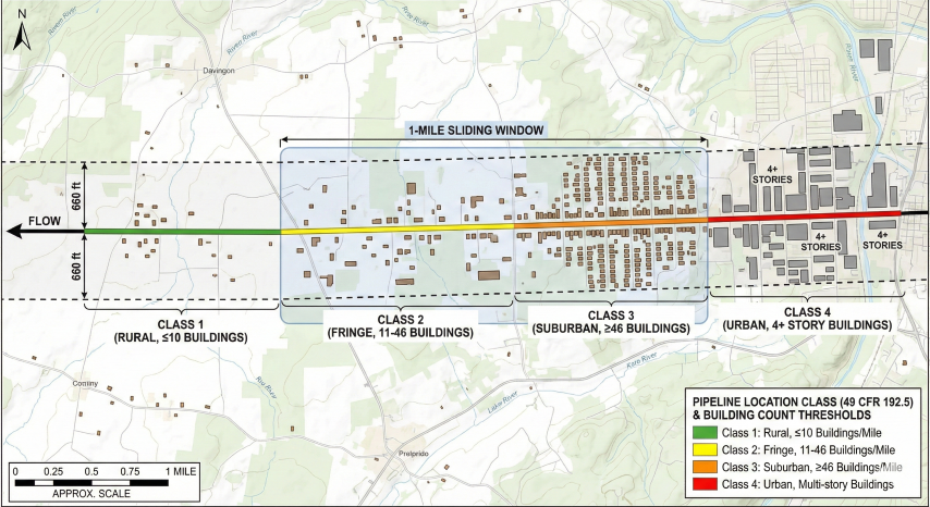
Federal regulations limit operating stress based on pipeline location class and potential consequences of failure. The design factor (F) directly sets the maximum allowable %SMYS.
49 CFR 192 – Natural Gas Pipelines
| Class | Design Factor | Max %SMYS | Description | Building Count |
|---|---|---|---|---|
| Class 1 | 0.72 | 72% | Rural/offshore | ≤10 per mile |
| Class 2 | 0.60 | 60% | Fringe areas | 11–46 |
| Class 3 | 0.50 | 50% | Suburban | ≥46 |
| Class 4 | 0.40 | 40% | Urban/high-rise | 4+ story buildings |
49 CFR 195 – Hazardous Liquid Pipelines
| Condition | Max %SMYS | Notes |
|---|---|---|
| General areas | 72% | Standard design limit |
| HCA (High Consequence Areas) | 72% | Requires integrity management |
| Road/rail crossings, casings | 60% | Reduced limit per §195.110 |
Hydrostatic Test Limits (ASME B31.8)
| Location Class | Min Test Pressure | Max Test Stress |
|---|---|---|
| Class 1, Div 1 | 1.25 × MAOP | 100% SMYS |
| Class 1, Div 2 | 1.25 × MAOP | 90% SMYS |
| Class 2 | 1.25 × MAOP | 90% SMYS |
| Class 3 & 4 | 1.40 × MAOP | 90% SMYS |
Class location change: If development increases building count, the pipeline may require pressure reduction, increased wall thickness, or protective measures to meet the lower %SMYS limit. Operators must conduct class location studies annually per 49 CFR 192.5.
4. Practical Applications
When %SMYS Calculations Are Required
- New pipeline design: Select wall thickness to meet target location class
- MAOP uprating: Verify stress remains within limits before increasing pressure
- Class location change: Determine pressure reduction requirements when building count increases
- Integrity assessment: Calculate stress at anomaly locations for repair prioritization
- Hydrostatic testing: Verify test pressure won't exceed stress limits
Wall Thickness Selection
For new construction, calculate minimum wall thickness for target operating stress:
Quick Reference: Maximum Pressure by Pipe Size
MAOP (psig) at different %SMYS limits for common pipe configurations:
| Pipe Size | Grade | 72% (Class 1) | 60% (Class 2) | 50% (Class 3) | 40% (Class 4) |
|---|---|---|---|---|---|
| 12.75" × 0.250" | X52 | 1,467 | 1,223 | 1,019 | 815 |
| 16" × 0.375" | X52 | 1,755 | 1,463 | 1,219 | 975 |
| 20" × 0.500" | X60 | 2,160 | 1,800 | 1,500 | 1,200 |
| 24" × 0.500" | X65 | 1,950 | 1,625 | 1,354 | 1,083 |
| 30" × 0.625" | X70 | 2,100 | 1,750 | 1,458 | 1,167 |
Values assume E = 1.0 (seamless/ERW) and T = 1.0 (≤250°F).
Joint Factor (E) Values
| Pipe Type | Joint Factor (E) |
|---|---|
| Seamless | 1.00 |
| ERW (Electric Resistance Welded) | 1.00 |
| Flash-welded | 1.00 |
| Submerged arc welded (DSAW) | 1.00 |
| Furnace lap welded | 0.80 |
| Furnace butt welded | 0.60 |
5. Integrity Assessment
Pipeline anomalies (corrosion, dents, cracks) reduce effective wall thickness, increasing local stress. %SMYS calculations are critical for evaluating remaining strength and prioritizing repairs.
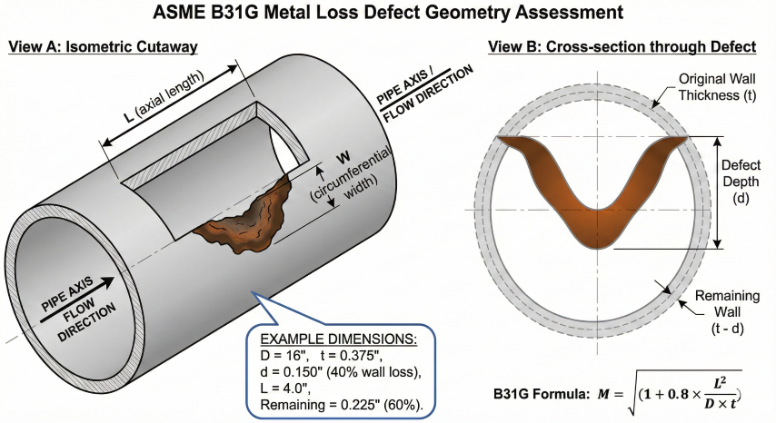
Remaining Strength per ASME B31G
For metal loss defects, calculate safe operating pressure using the modified B31G method (parabolic defect profile):
ILI Anomaly Response Guidelines
| Metal Loss Depth | Typical Response | Timeline |
|---|---|---|
| < 20% wall | Monitor, no immediate action | Next ILI cycle |
| 20–40% wall | Calculate remaining strength, schedule excavation | 1–2 years |
| 40–60% wall | Priority dig, evaluate for repair | 180 days |
| 60–80% wall | Immediate excavation, likely repair | 60 days |
| > 80% wall | Immediate investigation, pressure reduction | Immediate |
Timelines per 49 CFR 192.933 and operator integrity management programs.
Standards References
- 49 CFR Part 192 – Transportation of Natural and Other Gas by Pipeline
- 49 CFR Part 195 – Transportation of Hazardous Liquids by Pipeline
- ASME B31.8 – Gas Transmission and Distribution Piping Systems
- ASME B31G – Manual for Determining Remaining Strength of Corroded Pipelines
- API 5L – Specification for Line Pipe (46th Edition)
- API 1160 – Managing System Integrity for Hazardous Liquid Pipelines
Ready to use the calculator?
→ Launch Calculator