Design absorption towers for NGL recovery using lean oil circulation. Calculate absorption factors with the Kremser equation, select tower internals, and size regeneration systems using GPSA methods.
Lean oil absorption is a physical absorption process for recovering NGLs (propane, butanes, pentanes) from natural gas. A hydrocarbon solvent (lean oil) contacts the gas in a countercurrent tower, preferentially dissolving the heavier components.
Primary application
NGL Recovery
Recover C₃-C₅+ from rich gas streams for sale as NGL products.
Dew point control
Pipeline Spec
Meet hydrocarbon dew point specs (typically -20°F to 0°F cricondentherm).
Process economics
Moderate Capital
Lower capital than cryogenic; higher recovery than simple refrigeration.
Hybrid systems
Combined Processes
Often combined with refrigeration or turbo-expander for enhanced recovery.
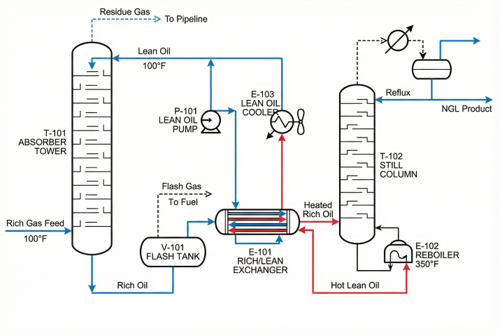
Typical lean oil absorption system showing absorber, flash tank, still, and heat exchangers.
Rich oil: Solvent leaving absorber saturated with absorbed C₃-C₅ components
Absorption factor (A): Ratio L/(K×V) that determines separation efficiency
K-value: Equilibrium ratio y/x for each component at operating conditions
Theoretical stages: Number of equilibrium stages required for target separation
Economic driver: For a 100 MMscfd plant with 6% C₃+ feed gas, lean oil absorption can recover 400-600 bbl/day of NGL products. At $40-60/bbl NGL pricing, this represents $6-13 million annual revenue. Proper design maximizes recovery while minimizing oil circulation and reboiler fuel costs.
2. Kremser Equation & K-Values
The Kremser equation (also called Kremser-Brown-Souders equation) provides a shortcut method for calculating absorption efficiency based on the absorption factor and number of theoretical stages.
Absorption Factor
Absorption Factor Definition:
A = L / (K × V)
Where:
A = Absorption factor (dimensionless)
L = Liquid molar flow rate (lbmol/hr)
V = Vapor molar flow rate (lbmol/hr)
K = Equilibrium K-value for the component
Design Guidelines:
• For good absorption: A > 1.4 (preferably 1.5-2.5)
• A < 1.0: Poor absorption, most of component stays in gas
• A = 1.0: 50% recovery at infinite stages
• A > 2.5: Diminishing returns, excessive oil circulation
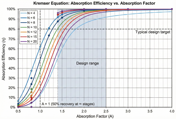
Kremser Equation
Fractional Absorption Efficiency:
η = (A^(N+1) - A) / (A^(N+1) - 1)
Where:
η = Fractional absorption (recovery) of the component
A = Absorption factor
N = Number of theoretical stages
Alternative form (solving for stages):
N = ln[(1 - 1/A)(η/(1-η)) + 1/A] / ln(A)
Special case when A = 1:
η = N / (N + 1)
Kremser equation showing absorption efficiency vs. absorption factor for various stage counts.
K-Value Fundamentals
The equilibrium K-value determines how a component distributes between vapor and liquid phases:
Equilibrium K-Value:
K = y / x
Where:
y = Mole fraction in vapor phase
x = Mole fraction in liquid phase
K-value depends on:
• Temperature (higher T → higher K)
• Pressure (higher P → lower K)
• Composition (lean oil type affects K slightly)
Simplified correlation (Wilson equation form):
K_i ≈ (P_c,i / P) × exp[5.373 × (1 + ω_i) × (1 - T_c,i / T)]
Where:
P_c = Critical pressure
T_c = Critical temperature
ω = Acentric factor
Typical K-Values for Lean Oil Absorption
Component
K @ 100°F, 400 psia
K @ 100°F, 600 psia
K @ 100°F, 800 psia
A @ OGR=2.5
Methane (C₁)
8.5
5.8
4.5
0.15-0.3
Ethane (C₂)
3.2
2.2
1.7
0.4-0.7
Propane (C₃)
1.4
0.95
0.75
1.5-2.5
i-Butane (iC₄)
0.52
0.35
0.28
4-8
n-Butane (nC₄)
0.40
0.28
0.22
5-10
Pentanes (C₅)
0.12
0.08
0.06
15-30
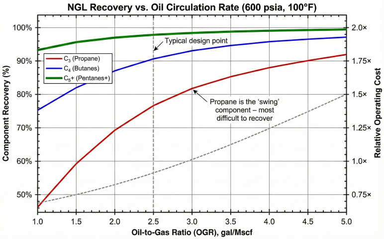
The "swing" component: Propane is typically the key component for lean oil absorption design. Its K-value is near 1.0 at typical conditions, making it the most difficult to absorb efficiently. Design the oil circulation to achieve target propane recovery; butanes and pentanes will have higher recovery automatically.
Example: Absorption Factor Calculation
Given:
Gas flow: 100 MMscfd at 600 psia, 100°F
Lean oil: C₁₀ average (MW = 142, ρ = 6.3 lb/gal)
Oil rate: 2.5 gal/Mscf (250,000 gal/day = 174 gpm)
Target: 85% C₃ recovery
Step 1: Calculate molar flow rates
V = 100 × 10⁶ scf/day ÷ 379.5 scf/lbmol ÷ 24 hr/day
V = 10,980 lbmol/hr
L = 250,000 gal/day × 6.3 lb/gal ÷ 142 lb/lbmol ÷ 24 hr/day
L = 462 lbmol/hr
Step 2: Get K-value for propane
K_C3 @ 100°F, 600 psia ≈ 0.95 (from chart or correlation)
Step 3: Calculate absorption factor
A_C3 = L / (K_C3 × V)
A_C3 = 462 / (0.95 × 10,980)
A_C3 = 0.044
This A is too low! Need more oil circulation.
Step 4: Required A for 85% recovery with 10 stages
Solving Kremser η = (A^(N+1)−A)/(A^(N+1)−1) for η = 0.85, N = 10:
A ≈ 0.90 (gives η ≈ 0.854)
Step 5: Required oil rate
L_required = A × K × V = 0.90 × 0.95 × 10,980 = 9,388 lbmol/hr
Oil rate = 9,388 × 142 ÷ 6.3 ÷ 60 = 3,525 gpm
This is impractical! The calculation shows we need:
OGR = 3,525 × 60 × 24 / 100,000 = 50.8 gal/Mscf
Conclusion: At these conditions, lean oil alone cannot achieve 85% C₃ recovery economically. Either increase pressure, lower temperature, or use a hybrid process.
3. Oil Circulation Rates
The oil-to-gas ratio (OGR) is the critical design parameter, directly affecting recovery, capital cost, and operating expense. Higher circulation improves recovery but increases pump, heat exchanger, and reboiler sizes.
Oil-to-Gas Ratio
From Absorption Factor:
OGR = (A × K × V × MW_oil) / (ρ_oil × Q_gas × 1000)
Where:
OGR = Oil-to-gas ratio (gal lean oil / Mscf gas)
A = Target absorption factor for propane
K = K-value for propane at operating conditions
V = Vapor molar flow (lbmol/hr)
MW_oil = Lean oil molecular weight (lb/lbmol)
ρ_oil = Lean oil density (lb/gal)
Q_gas = Gas flow rate (MMscfd)
Simplified estimation:
OGR ≈ 2.0 × (MW_oil/150) × (600/P) × (T/100) for 80% C₃ recovery
OGR ≈ 3.5 × (MW_oil/150) × (600/P) × (T/100) for 90% C₃ recovery
Typical ranges:
• Low pressure (400 psia): 3-5 gal/Mscf
• Medium pressure (600 psia): 2-4 gal/Mscf
• High pressure (800+ psia): 1.5-3 gal/Mscf
Component Recovery vs. Oil Rate
OGR (gal/Mscf)
C₃ Recovery
C₄ Recovery
C₅+ Recovery
Relative Cost
1.5
55-65%
78-85%
94-97%
0.75×
2.0
65-75%
84-90%
96-98%
1.00× (base)
2.5
75-82%
88-93%
97-99%
1.25×
3.0
82-88%
92-95%
98-99.5%
1.50×
4.0
88-93%
95-97%
99-99.8%
2.00×
Component recovery increases with oil circulation rate; C₃ is most sensitive.
Rich Oil Composition
NGL Loading in Rich Oil:
Rich oil NGL content = (Total NGL absorbed) / (Oil circulation + NGL absorbed) × 100%
Typical values:
• Low circulation: 15-25% NGL in rich oil
• High circulation: 5-15% NGL in rich oil
Design limits:
• Rich oil > 25% NGL: May cause foaming in still
• Rich oil > 30% NGL: Vapor pressure too high, flash losses increase
Rich oil gravity shift:
Lean oil API: 38-45°
Rich oil API: 45-55° (lighter due to dissolved C₃-C₅)
This density change affects pump sizing and flash drum design.
Economic Optimization
The optimal oil rate balances NGL revenue against operating costs:
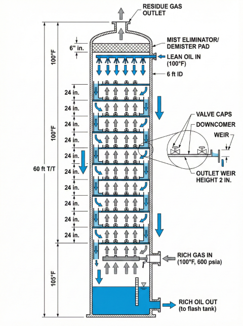
Absorption towers provide countercurrent vapor-liquid contact. Design involves selecting the number of stages, choosing internals (trays or packing), and sizing the column diameter.
Number of Stages
Theoretical Stages (from Kremser):
For target recovery η and absorption factor A:
N = ln[(1 - 1/A)(η/(1-η)) + 1/A] / ln(A)
Typical stage requirements:
• 70% C₃ recovery: 6-8 theoretical stages
• 80% C₃ recovery: 8-10 theoretical stages
• 85% C₃ recovery: 10-12 theoretical stages
• 90% C₃ recovery: 12-15 theoretical stages
Actual Trays:
N_actual = N_theoretical / E_tray
Typical tray efficiency: 65-80%
For 10 theoretical stages at 70% efficiency:
N_actual = 10 / 0.70 = 14.3 → 15 trays
Add 10-20% extra trays for turndown flexibility.
Selection guideline: For new lean oil absorbers with diameter > 4 ft, trayed towers are preferred due to better fouling tolerance and easier inspection. Structured packing is used in retrofits where pressure drop reduction or capacity increase is needed without replacing the vessel.
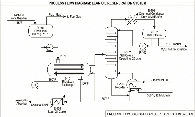
5. Regeneration Systems
Rich oil must be regenerated (stripped) to remove absorbed light ends before recirculation. The still is a reboiled distillation column that produces lean oil bottoms and NGL overhead product.
System Components
Flash tank: Reduces rich oil pressure (50-150 psig) to recover methane and ethane as vapor
Rich/lean exchanger: Preheats rich oil using hot lean oil, saves reboiler fuel
Still (stripper): 8-15 tray column, reboiled at 300-400°F
Overhead condenser: Produces liquid NGL product plus reflux
Lean oil cooler: Cools regenerated oil before returning to absorber
Lean oil regeneration system with flash tank, still, and heat integration.
Lean Oil Specifications:
Critical parameters:
• C₃ content: < 1-2 mol% (lower is better)
• C₄ content: < 3-5 mol%
• Vapor pressure: < 5 psia @ absorber temperature
• API gravity: 35-45° (stable operating range)
Oil Makeup:
Losses occur via:
• Vapor losses in absorber (0.01-0.1%/day)
• Entrainment in residue gas
• NGL product contamination
Makeup rate: 0.1-0.5% of circulation per day
Sources:
• Plant condensate stabilizer bottoms
• Purchased absorption oil (kerosene, gas oil)
Operating economics: The still reboiler typically accounts for 60-80% of lean oil absorption operating cost. Key optimizations: (1) maximize rich/lean heat exchange to reduce duty, (2) optimize still pressure to balance product quality vs. fuel, (3) maintain proper reflux to prevent C₄+ losses while minimizing excess heating.
What is the Kremser equation in lean oil absorption?+
The Kremser equation relates the number of theoretical stages, absorption factor, and component recovery in an absorption column. It allows engineers to calculate the required number of stages for a target NGL recovery given the oil circulation rate and K-values.
How is the absorption factor calculated for NGL recovery?+
The absorption factor is calculated as the ratio of the lean oil molar flow rate to the product of the gas molar flow rate and the equilibrium K-value for each component. An absorption factor greater than one is needed for effective recovery of a given component.
What determines the oil circulation rate in a lean oil plant?+
The oil circulation rate is set by the heaviest component targeted for recovery and its required recovery percentage. Higher oil rates increase recovery but also increase reboiler duty and pumping costs, so economic optimization balances recovery against operating expenses.
How is a lean oil absorption tower designed?+
Tower design involves selecting the number of theoretical stages from the Kremser equation, sizing the diameter based on gas velocity and flooding limits, and choosing between trays and packing. The regeneration system is then designed to strip absorbed hydrocarbons and return lean oil to the absorber.