1. MAOP Definition
MAOP is the maximum pressure at which a pipeline may be operated under federal regulations. For natural gas pipelines, 49 CFR Part 192 governs MAOP determination. The operating pressure must never exceed MAOP during normal operations.
Regulatory Framework
| Regulation/Standard | Application |
|---|---|
| 49 CFR Part 192 | Natural gas transmission and distribution (federal law) |
| 49 CFR Part 195 | Hazardous liquids (oil, NGL, CO₂) |
| ASME B31.8 | Gas transmission and distribution piping systems |
| ASME B31.4 | Pipeline transportation of liquid hydrocarbons |
| API 1111 | Offshore pipelines |
2. Design Formula
The fundamental equation for MAOP is based on Barlow's formula modified with design factors:
Rearranged Forms
Common SMYS Values
| Grade | SMYS (psi) | Specification |
|---|---|---|
| Grade B | 35,500 | API 5L, ASTM A53/A106 |
| X42 | 42,000 | API 5L |
| X46 | 46,000 | API 5L |
| X52 | 52,000 | API 5L |
| X56 | 56,000 | API 5L |
| X60 | 60,000 | API 5L |
| X65 | 65,000 | API 5L |
| X70 | 70,000 | API 5L |
| X80 | 80,000 | API 5L |
3. Design Factors
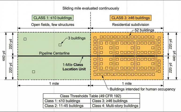
Location Class (Design Factor F)
Location class is determined by population density within a "class location unit"—a 1-mile segment with a 220-yard corridor on each side of the pipeline.
| Class | F | %SMYS | Description |
|---|---|---|---|
| Class 1 | 0.72 | 72% | ≤10 buildings; rural, undeveloped |
| Class 2 | 0.60 | 60% | 11–46 buildings; fringe areas, farms |
| Class 3 | 0.50 | 50% | ≥46 buildings or within 100 yards of buildings with ≥20 people |
| Class 4 | 0.40 | 40% | ≥4-story buildings above ground |
Joint Factor (E)
| Pipe Type | E Factor |
|---|---|
| Seamless | 1.00 |
| ERW (Electric Resistance Welded) | 1.00 |
| Flash Welded | 1.00 |
| DSAW (Double Submerged Arc Welded) | 1.00 |
| Furnace Lap Welded | 0.80 |
| Furnace Butt Welded | 0.60 |
Temperature Factor (T)
| Temperature (°F) | T Factor |
|---|---|
| ≤250 | 1.000 |
| 300 | 0.967 |
| 350 | 0.933 |
| 400 | 0.900 |
| 450 | 0.867 |
4. Pressure Testing
New pipelines must be pressure tested before operation. The test pressure validates the MAOP and ensures construction quality.
Test Pressure Requirements (49 CFR 192.619 Table 1)
For pipelines installed on or after July 1, 2020:
| Class | Test Medium | Minimum Test Pressure |
|---|---|---|
| Class 1 | Air, gas, or water | 1.25 × MAOP |
| Class 2 | Air, gas, or water | 1.25 × MAOP |
| Class 3 | Water (hydrostatic) | 1.50 × MAOP |
| Class 4 | Water (hydrostatic) | 1.50 × MAOP |
Test Duration
- Hydrostatic (water): Minimum 8 hours at test pressure
- Pneumatic (air/gas): Minimum 24 hours (more stringent due to stored energy hazard)
⚠ Wall stress during test: Ensure test pressure does not exceed 100% SMYS in the pipe wall. Calculate: S_test = P_test × D / (2 × t). If S_test > SMYS, reduce test pressure or the pipe may yield permanently.
Example: MAOP and Test Pressure
Given: 12.75" OD, 0.375" nominal wall, X52 pipe in Class 2 location
5. MAOP Determination Methods
49 CFR 192.619 allows several methods to establish MAOP, depending on available records:
Method 1: Design Formula
Use the design formula (Section 2) when all parameters are known from records:
- Pipe specification (SMYS, diameter, wall thickness)
- Seam type (joint factor)
- Location class
Method 2: Test Pressure
MAOP based on highest test pressure:
Method 3: Highest Actual Operating Pressure
For pipelines in service before certain dates with incomplete records:
- MAOP = highest actual operating pressure during 5 years before July 1, 1970
- Subject to additional requirements (ILI, ECDA, etc.)
Method 4: Pipe Replacement
For replaced pipe segments, use design formula with known specifications.
References
- 49 CFR Part 192 – Transportation of Natural and Other Gas by Pipeline
- ASME B31.8 – Gas Transmission and Distribution Piping Systems
- PHMSA Advisory Bulletins on MAOP Verification
- API 1160 – Managing System Integrity for Hazardous Liquid Pipelines
Ready to use the calculator?
→ Launch Calculator