Understand the relationship between horsepower and torque, size motors and engines for compressors and pumps, select gearboxes and couplings, and calculate starting torque and locked rotor current.
Estimate starting current and locked rotor torque.
1. Overview & Applications
Horsepower and torque are fundamental to sizing and selecting prime movers (motors, engines, turbines) for compressors, pumps, and other rotating equipment in midstream facilities.
Compressor drives
Centrifugal/reciprocating
Motor or engine sizing based on horsepower demand at operating conditions.
Pump drives
Centrifugal/positive displacement
Hydraulic power requirements plus mechanical efficiency losses.
Gearbox selection
Speed reduction
Match motor speed to driven equipment speed with proper service factor.
Starting analysis
Locked rotor current
Electrical system must handle inrush current during motor startup.
Key Concepts
Horsepower (HP): Rate of doing work; 1 HP = 550 ft-lb/s = 33,000 ft-lb/min = 745.7 watts
Speed (N): Revolutions per minute (RPM); synchronous speed = 120f/p where f=frequency, p=poles
Efficiency (η): Output/input power ratio; NEMA Premium motors: 91-96% depending on size
Service Factor (SF): Continuous overload capacity; typically 1.15 for TEFC motors per NEMA MG-1
Why HP and torque matter: Undersizing a motor results in overload trips and equipment failure. Oversizing wastes capital and reduces efficiency at low loads. Proper sizing requires understanding both steady-state and transient torque demands.
2. Horsepower-Torque Relationship
The fundamental relationship between mechanical power, torque, and rotational speed is derived from the definition of work and power.
Fundamental Equation
Horsepower-Torque Relationship:
HP = (T × RPM) / 5252
Where:
HP = Horsepower (mechanical)
T = Torque (lb·ft)
RPM = Rotational speed (revolutions per minute)
5252 = Conversion constant (33000 / 2π)
Alternatively:
T = (HP × 5252) / RPM
Or in SI units:
P (kW) = (T × RPM) / 9549
Where T is in N·m
Derivation
From First Principles:
Power = Work / Time
Work (rotational) = Force × Distance = Torque × Angle
P = T × ω (where ω = angular velocity in rad/s)
Converting to HP and RPM:
ω (rad/s) = (2π × RPM) / 60
P (ft·lb/s) = T (lb·ft) × (2π × RPM) / 60
HP = P / 550 (550 ft·lb/s = 1 HP)
HP = [T × (2π × RPM) / 60] / 550
HP = T × RPM × (2π / 33000)
HP = T × RPM / 5252
Where 5252 = 33000 / (2π)
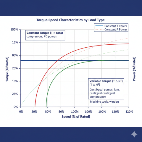
Torque vs. Speed Characteristics
Torque vs speed load profiles for different equipment types. Centrifugal loads (T∝N²) have cubic power relationship with speed, while constant torque loads have linear power increase.
Calculate torque required for a 500 HP motor operating at 1800 RPM:
Given:
HP = 500
RPM = 1800
T = (HP × 5252) / RPM
T = (500 × 5252) / 1800
T = 2,626,000 / 1800
T = 1459 lb·ft
Check:
HP = (1459 × 1800) / 5252 = 500 HP ✓
At half speed (900 RPM) for same power:
T = (500 × 5252) / 900 = 2918 lb·ft (double the torque)
Power Forms and Conversions
Common Power Units:
1 HP (mechanical) = 550 ft-lb/s = 33,000 ft-lb/min
1 HP = 745.7 watts (745.699... exact)
1 HP = 0.7457 kW
1 HP = 2545 Btu/hr
1 kW = 1.341 HP
Brake Horsepower (BHP):
BHP = Power delivered to shaft (measured by dynamometer or calculated)
Indicated Horsepower (IHP):
IHP = Theoretical power from cylinder pressure (reciprocating compressors/engines)
Electrical Input Power (3-phase):
kW_in = (HP × 0.7457) / η
Amps = (HP × 746) / (√3 × V × η × PF)
Where:
η = Motor efficiency (0.90–0.96 typical)
PF = Power factor (0.85–0.92 at full load)
V = Line voltage (460V standard US industrial)
3. Motor/Engine Sizing
Proper motor or engine sizing requires calculating power demand at operating conditions and applying appropriate safety factors for transient loads, efficiency losses, and service conditions.
Step-by-Step Motor Selection:
1. Calculate brake horsepower (BHP) at operating conditions
2. Apply service factor: HP_rated = BHP / SF
- SF = 1.0 (continuous duty, constant load)
- SF = 1.15 (intermittent duty, standard service)
- SF = 1.25 (heavy duty, frequent starts)
3. Select next standard motor size:
Standard HP ratings: 1, 1.5, 2, 3, 5, 7.5, 10, 15, 20, 25, 30, 40, 50,
60, 75, 100, 125, 150, 200, 250, 300, 350, 400, 450, 500, 600, 700,
800, 900, 1000, 1250, 1500, 1750, 2000, 2500, 3000
4. Verify motor can handle peak load:
HP_peak < HP_rated × SF
5. Check thermal rating (nameplate temperature rise)
Motor Efficiency and Power Factor
Motor Size (HP)
NEMA Premium Efficiency
Typical Power Factor
Full Load Current (460V)
10
91.7%
0.85
14 A
50
93.6%
0.87
62 A
100
95.0%
0.89
120 A
250
95.8%
0.90
288 A
500
96.2%
0.91
570 A
1000
96.5%
0.92
1140 A
Example: Compressor Motor Sizing
Size a motor for a centrifugal compressor with the following operating conditions:
Given:
Q = 5000 ACFM (inlet)
P₁ = 100 psia
P₂ = 500 psia
T₁ = 80°F = 540°R
η_adi = 0.80
k = 1.27
Calculate compression ratio:
r = 500 / 100 = 5.0
Calculate BHP:
BHP = (5000 × 100 × 1.27/(1.27-1) × 1/(0.80 × 229)) × [(5.0^0.213) - 1]
BHP = (5000 × 100 × 4.70 / 183.2) × [1.408 - 1]
BHP = 12,837 × 0.408
BHP = 5238 HP
Apply service factor (continuous duty, centrifugal):
SF = 1.15
HP_rated = 5238 / 1.15 = 4555 HP
Select standard motor: 5000 HP (next size up)
Verify peak load capacity:
HP_peak (startup surge) ≈ 1.10 × 5238 = 5762 HP
HP_available = 5000 × 1.15 = 5750 HP (marginal — consider 6000 HP)
Select: 5000 HP if startup is unloaded, or 6000 HP for full-load start margin
Service factor importance: The motor service factor allows brief overloads without damage. A 1.15 SF motor rated at 100 HP can deliver 115 HP continuously at rated voltage and frequency. However, operating above nameplate HP increases temperature rise and reduces motor life.
4. Gearbox and Coupling Selection
Gearboxes provide speed reduction or increase between driver and driven equipment. Flexible couplings accommodate misalignment and dampen torsional vibrations.
Rated Gearbox Torque:
T_rated = (T_operating × SF_AGMA) / η_gearbox
Where:
T_operating = Operating torque at output shaft (lb·ft)
SF_AGMA = Service factor from AGMA 6010 (see table above)
η_gearbox = Gearbox mechanical efficiency (0.95–0.98)
Thermal Rating Check:
HP_thermal = k × (T_rated / 1000)^1.5 × (N_output / 100)^0.5
Where k depends on gearbox cooling method:
k = 1.0 (natural convection)
k = 1.5 (forced air cooling)
k = 2.5 (oil cooling with heat exchanger)
Verify: HP_operating < HP_thermal
Coupling Selection
Flexible couplings connect driver and driven shafts while accommodating misalignment, transmitting torque, and dampening vibrations.
Coupling Torque Rating:
T_coupling = T_operating × SF_coupling
Where:
SF_coupling = Coupling service factor:
- 1.5 (normal service, electric motor drive)
- 2.0 (reciprocating equipment)
- 2.5 (heavy shock loads)
Misalignment Capacity:
Parallel offset: 0.010–0.030 in (gear/grid couplings)
Angular: 0.5°–1.5° (elastomeric couplings)
Axial: ±0.125–0.250 in (typical)
Torsional Stiffness:
K_torsional = T / θ (lb·ft/rad)
Where:
T = Applied torque (lb·ft)
θ = Angular deflection (radians)
Soft couplings (elastomeric): K = 10³–10⁵ lb·ft/rad
Stiff couplings (gear): K = 10⁶–10⁷ lb·ft/rad
Coupling Types Comparison
Coupling Type
Torque Capacity
Misalignment
Damping
Application
Gear (lubricated)
Very high
Moderate
Low
Large compressors, high torque
Grid
High
Moderate
Moderate
General purpose, pumps
Elastomeric
Low-moderate
High
High
Small pumps, vibration isolation
Disc pack
Moderate
Low
Very low
High-speed, precise alignment
5. Starting Torque & Power Factor
Electric motors draw high current during startup (locked rotor condition) and produce characteristic torque profiles as they accelerate to rated speed.
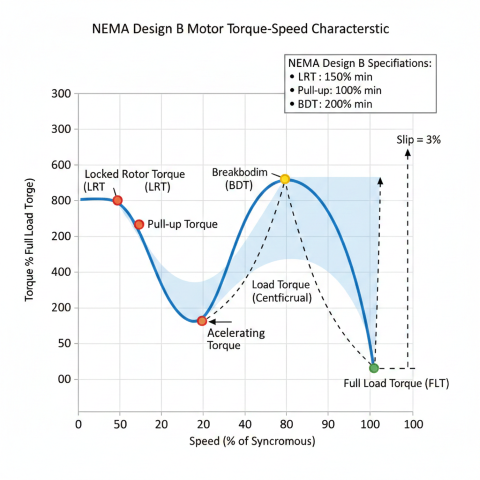
Motor Torque-Speed Curve
NEMA Design B induction motor torque-speed curve showing key operating points: LRT (150% min), pull-up (100% min), and breakdown torque (200% min). The shaded area represents accelerating torque available to bring load up to speed.
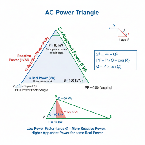
AC power triangle illustrating the relationship between real power (kW), reactive power (kVAR), and apparent power (kVA). Low power factor increases apparent power and current draw for the same useful work.
Power Factor Definition:
PF = cos(φ) = P / S
Where:
P = Real power (kW) - does actual work
S = Apparent power (kVA) - total power drawn
φ = Phase angle between voltage and current
Power Triangle:
S² = P² + Q²
Where:
Q = Reactive power (kVAR) - magnetizing current
Motor Power Factor vs Load:
PF(load) ≈ PF_rated × (Load% / 100)^0.5
At 100% load: PF = 0.85–0.92 (typical)
At 75% load: PF ≈ 0.86 × (0.75)^0.5 = 0.75
At 50% load: PF ≈ 0.86 × (0.50)^0.5 = 0.61
At 25% load: PF ≈ 0.86 × (0.25)^0.5 = 0.43
Low PF at light loads → poor efficiency, high reactive current
Motor Efficiency vs Load
Load (%)
Efficiency (Premium Motor)
Power Factor
kW Input (100 HP motor)
25%
91.0%
0.55
20.5 kW
50%
94.5%
0.70
39.5 kW
75%
95.5%
0.82
58.5 kW
100%
95.0%
0.88
78.5 kW
115% (SF)
94.0%
0.89
91.0 kW
Voltage Drop During Starting
System Voltage Drop:
ΔV% = (LRA / SC_available) × 100%
Where:
LRA = Locked rotor amps (starting current)
SC_available = System short-circuit current capacity (amps)
Acceptable limits:
ΔV < 10% (large utility grid)
ΔV < 15% (weak grid or remote location)
ΔV < 5% (sensitive equipment on same bus)
Example:
500 HP motor:
FLA = 570 A @ 460V
LRA = 6.5 × 570 = 3705 A
System SC capacity = 25,000 A
ΔV% = (3705 / 25000) × 100% = 14.8%
Result: May require soft starter or larger transformer
Practical Considerations
Motor acceleration time: Typically 5–15 seconds for centrifugal loads; WK² (inertia) of driven equipment affects acceleration
Thermal limits: Number of starts per hour limited by motor thermal capacity (typically 2–3 starts/hour for large motors)
VFD benefits: Reduced starting current, adjustable speed, energy savings at partial load, but adds harmonics and requires motor insulation rating
Power factor correction: Capacitor banks improve PF but must be sized to avoid resonance; disconnect during starting to prevent voltage spike
Starting current impact: A 500 HP motor drawing 6.5 × FLA during startup requires 3700 A inrush current. This creates voltage sag affecting other equipment and requires proper transformer sizing, cable selection, and protective relay coordination. Soft starters or VFDs reduce starting current to 2–4 × FLA.