1. Overview
Nitrogen pressure testing verifies pipeline structural integrity and leak tightness before commissioning or after repair. Nitrogen is preferred over air (safety) and water (ease of removal, no freezing concerns).
Strength Test
Verify Wall Integrity
Tests pipe body, welds, and fittings at pressures exceeding MAOP.
Leak Test
Detect Leakage
Identifies leaks at joints, valves, and connections at operating pressure.
Safety
Inert Gas
No fire/explosion risk compared to air testing for hydrocarbon service.
Practical
No Drying Required
Eliminates water disposal and pipeline drying procedures.
Regulatory Framework
| Standard | Scope | Key Sections |
|---|---|---|
| ASME B31.8 | Gas transmission & distribution | §841.3, §845.2 |
| 49 CFR 192 | Federal pipeline safety (DOT) | §192.505-517 |
| ASME B31.4 | Liquid petroleum pipelines | §437 (with approval) |
| API 1104 | Pipeline welding | Appendix A |
2. Test Pressure Requirements
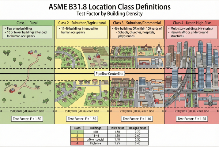
Test pressure depends on location class and intended MAOP per ASME B31.8 and 49 CFR Part 192.
ASME B31.8 Test Factors
Test Pressure Limits
| Limiting Factor | Maximum Test Pressure |
|---|---|
| Pipe body | 100% SMYS (90% recommended) |
| Valves | Cold working pressure (CWP) rating |
| Flanges (B16.5) | Pressure rating at test temperature |
| Instruments | Maximum rated pressure |
Example: Test Pressure Calculation
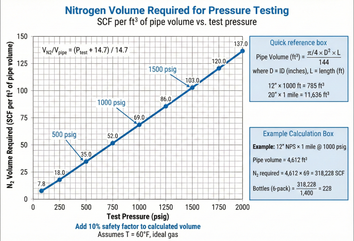
3. Nitrogen Volume Calculation
Nitrogen volume required depends on pipe volume, test pressure, and temperature. Calculations use real gas law for accuracy at high pressures.
Basic Formula
Standard Nitrogen Bottle Sizes
| Container | Volume (SCF) | Pressure (psig) | Typical Use |
|---|---|---|---|
| K-Cylinder | 251 | 2,400 | Small tests, makeup |
| T-Cylinder | 330 | 2,640 | Small tests |
| 6-Pack | 1,506 | 2,400 | Medium tests |
| 12-Pack | 3,012 | 2,400 | Medium-large tests |
| 16-Pack | 4,016 | 2,400 | Large tests |
| Tube Trailer | ~180,000 | 2,400 | Major pipeline tests |
Example: N₂ Bottle Calculation
Compressibility Factor (Z)
Nitrogen behaves nearly ideally at pipeline test conditions (Tr > 2.0). Z stays close to 1.000 across the typical pressure range:
| Pressure (psia) | Z @ 60°F | Z @ 100°F |
|---|---|---|
| 14.7 (atm) | 1.000 | 1.000 |
| 500 | 0.998 | 0.999 |
| 1000 | 0.997 | 0.998 |
| 1500 | 0.997 | 0.998 |
| 2000 | 0.998 | 0.999 |
| 2500 | 1.000 | 1.001 |
For most pipeline tests (P < 2000 psig), ideal gas assumption (Z = 1.0) is within 0.3% accuracy. The calculator applies a Pitzer correlation for Z automatically.
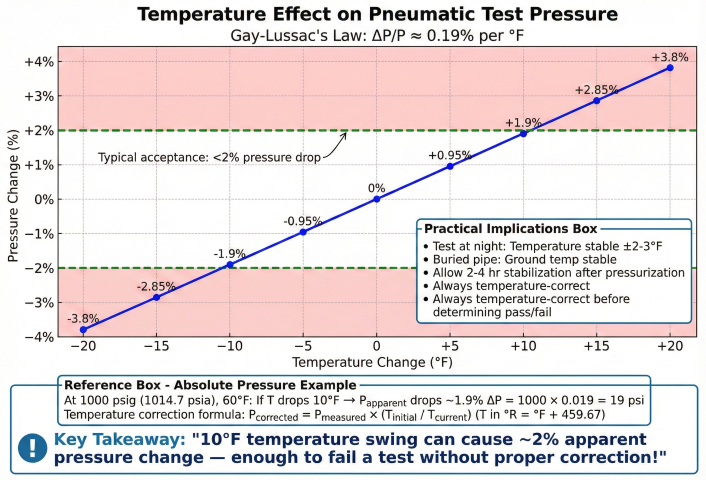
4. Temperature Corrections
Pneumatic test pressure varies significantly with temperature. Temperature corrections are essential to distinguish real leaks from thermal effects.
Temperature Correction Formula
Temperature Effect Magnitude
| ΔT (°F) | ΔP @ 1000 psig | % Change |
|---|---|---|
| ±1 | ±2.0 psi | ±0.20% |
| ±5 | ±9.8 psi | ±1.0% |
| ±10 | ±19.5 psi | ±2.0% |
| ±20 | ±39 psi | ±3.9% |
Example: Temperature Correction
Minimizing Temperature Effects
- Buried pipe: Test after backfill—ground temperature stable within ±2-3°F
- Night testing: Minimal solar heating, temperature more stable
- Insulate exposed sections: Reduce radiative heating/cooling
- Allow stabilization: Wait 2-4 hours after pressurization before starting hold time
5. Test Procedures
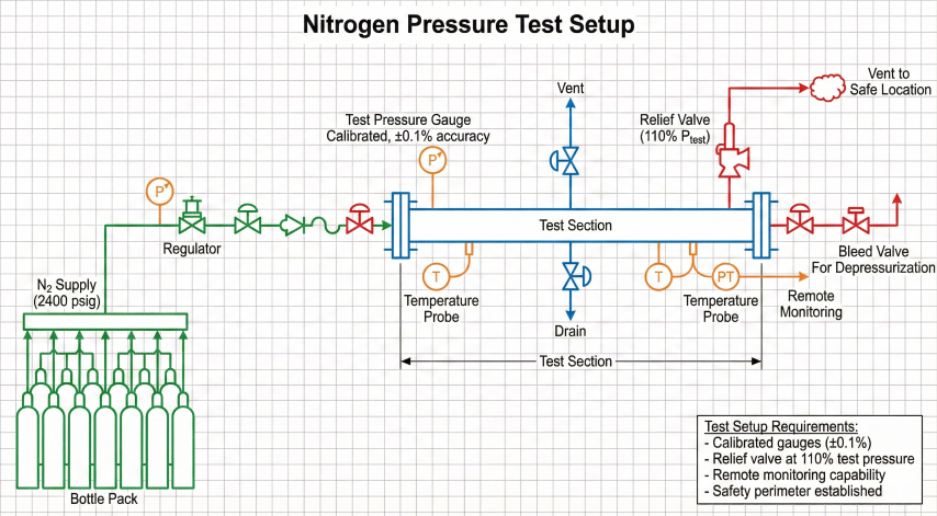
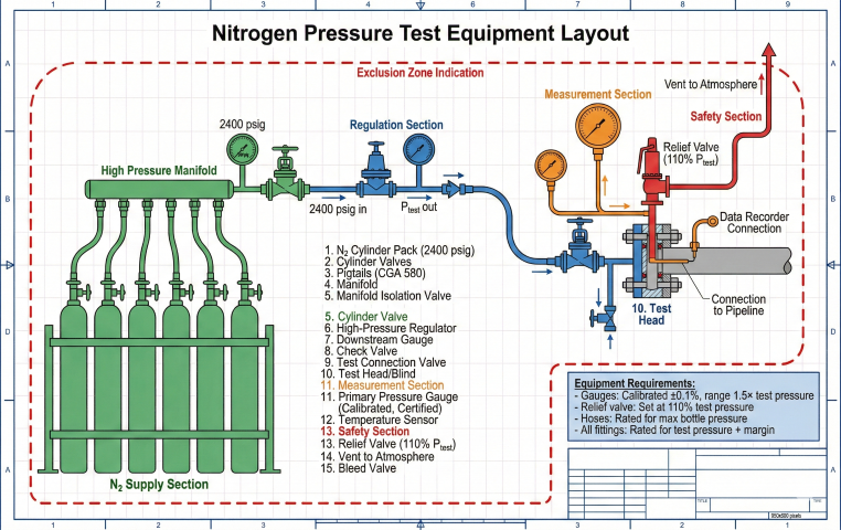
Pre-Test Checklist
- Install test heads/blinds at section boundaries
- Verify all valves, flanges, instruments rated for test pressure
- Install calibrated pressure gauges (±0.1% accuracy) and temperature sensors
- Set relief valves at 110% of test pressure
- Open high-point vents, verify low-point drains accessible
- Establish safety perimeter, brief personnel
Pressurization Sequence
Hold Time Requirements
49 CFR 192.507 requires a minimum 1-hour hold for pneumatic strength tests. The extended hold times below are typical industry practice for leak detection and temperature stabilization:
| Pipe Size (NPS) | Typical Hold Time | Extended (Best Practice) |
|---|---|---|
| ≤ 4" | 4 hours | 4 hours |
| 4" to 12" | 6 hours | 6-8 hours |
| 12" to 24" | 8 hours | 8-12 hours |
| > 24" | 8 hours | 12-24 hours |
| HCA (High Consequence Area) | 8 hours | 24 hours |
Acceptance Criteria
| Test Type | Acceptance | Failure |
|---|---|---|
| Strength test | No rupture, P drop <5% | Rupture or excessive drop |
| Leak test | No visible leaks, P drop <2% (temp corrected) | Visible leaks or P drop >5% |
| HCA | No detectable leaks, P drop <1% | Any leak or P drop >2% |
Depressurization
- Maximum rate: 100 psi/min (NPS ≤ 12), 50 psi/min (NPS > 12)
- Open high-point vents to prevent vacuum formation
- Vent to safe location away from personnel (Joule-Thomson cooling at vent)
- Monitor for freezing at vent discharge
Documentation Requirements
Per ASME B31.8 §841.3.4 and 49 CFR §192.517:
- Pressure vs. time data (15-minute intervals minimum)
- Temperature vs. time data at multiple points
- Pipe specifications: NPS, WT, grade, SMYS
- Test parameters: MAOP, test pressure, test factor, hold time
- Gauge calibration certificates
- Temperature-corrected results and acceptance determination
- Signature of test supervisor and inspector
Ready to use the calculator?
→ Launch Calculator