1. Overview
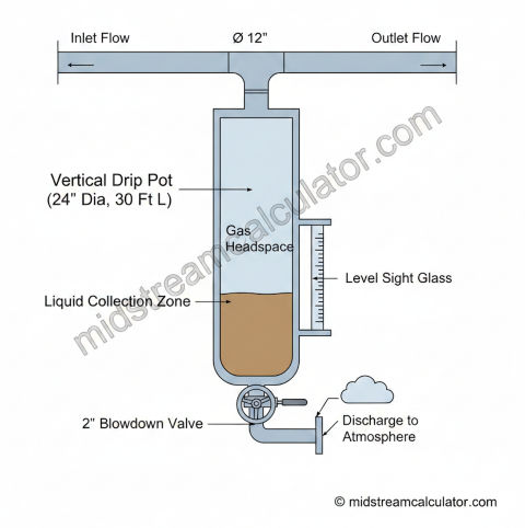
Drip pots (drips, condensate traps) collect liquids that condense from gas streams in pipelines. Periodic blowdown removes accumulated liquids to prevent operational problems.
Why Drips Are Needed
Liquid slugging
Equipment Protection
Prevents compressor damage and meter errors from liquid carry-through.
Hydrate prevention
Flow Assurance
Reduces hydrate formation risk at low temperatures.
Corrosion control
Integrity
Eliminates water pooling that causes internal corrosion.
Common Drip Locations
| Location | Purpose | Typical Size |
|---|---|---|
| Pipeline low points | Collect condensate from grade changes | 10-30 bbl |
| Compressor suction | Protect compressor from liquid slugs | 20-50 bbl |
| Meter station inlet | Ensure dry gas for accurate metering | 10-20 bbl |
| Regulator upstream | Prevent liquid carryover through valve | 10-30 bbl |
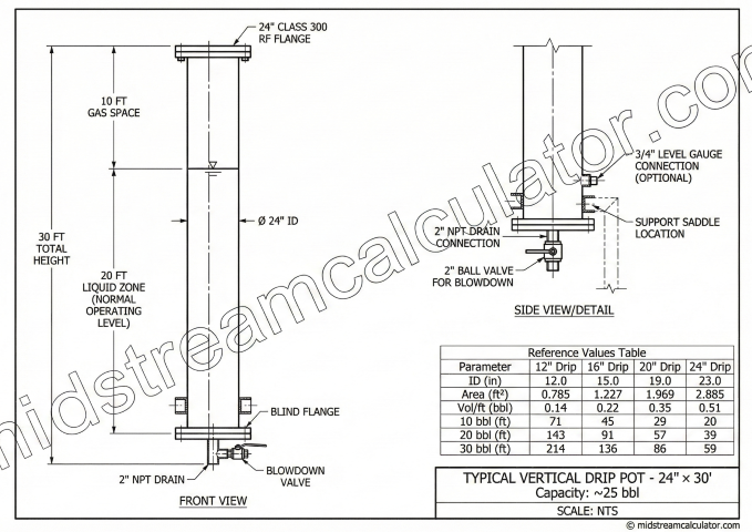
2. Drip Pot Sizing
Drip sizing is based on condensate rate, desired blowdown frequency, and a safety factor for upsets.
Sizing Formula
Vertical Drip Dimensions
| Pipe Diameter | Volume per ft | 10 bbl Length | 20 bbl Length |
|---|---|---|---|
| 12" | 0.14 bbl/ft | 71 ft | 143 ft |
| 16" | 0.25 bbl/ft | 40 ft | 80 ft |
| 20" | 0.39 bbl/ft | 26 ft | 52 ft |
| 24" | 0.56 bbl/ft | 18 ft | 36 ft |
Condensate Sources
- Retrograde condensation: Pressure drop through regulators causes temperature drop (JT cooling) and liquid dropout
- Water condensation: Cooling below water dewpoint as gas travels through buried pipeline
- Carryover: Liquid entrainment from upstream separators during slug events
3. Gas Loss Calculation
Gas is vented during blowdown operations. Accurate loss estimation is required for emissions reporting (EPA Subpart W) and production accounting.
Engineering Method
Field Estimation Method
When detailed operating data isn't available, a screening estimate keys off blow counts (each blow vents ≈ the pot's gas inventory at line pressure — not a published emission-factor table; use the volume method for reportable figures):
| Component | Base Factor | Basis |
|---|---|---|
| Wet blow | 2.0 MCF/blow | Each blow vents the pot's gas inventory (≈ V_pot · P_abs/P_std), 500 psig reference |
| Dry blow | 2.0 MCF/blow | Same pot-inventory basis as a wet blow — liquid presence does not change vented gas |
| Dissolved gas | 1.05 scf/gal | Gas released from condensate at 100 psig (scales with P^0.5) |
Pressure Adjustment
Emissions Conversion
4. Blowdown Procedures
Safe blowdown procedures protect personnel and minimize environmental impact.
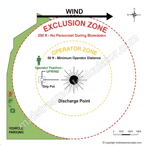
Pre-Blowdown Checklist
- Area clear: No personnel within 300 ft of discharge point
- Wind check: Discharge direction favorable (downwind from operator)
- Ignition sources: No vehicles, equipment, or smoking nearby
- Valve inspection: Exercise blowdown valve to verify operation
- PPE: FRC, safety glasses, chemical-resistant gloves
Blowdown Steps
Blowdown Frequency Guidelines
| Condensate Rate | Frequency |
|---|---|
| < 0.5 bbl/day | Monthly |
| 0.5-2 bbl/day | Weekly |
| 2-5 bbl/day | Every 2-3 days |
| > 5 bbl/day | Daily or automatic |
5. Safety & Compliance
Primary Hazards
| Hazard | Control |
|---|---|
| High-pressure gas release | Stand clear, use extended handles, hearing protection |
| Flammable atmosphere | Clear ignition sources, verify wind direction |
| H₂S (sour gas) | Personal monitors, buddy system, SCBA available, upwind position |
| Liquid hydrocarbon contact | FRC, chemical gloves, eye protection |
| JT freezing | Insulated gloves, slow valve opening |
H₂S Considerations
For sour gas service (H₂S > 100 ppm in gas):
- Two-person minimum (buddy system)
- Personal H₂S monitors with audible alarms
- SCBA equipment available on-site
- Wind indicator visible (sock or ribbon)
- Increase exclusion zone to 500+ ft
- Consider closed-loop blowdown to recovery tank
Environmental Compliance
Ready to use the calculator?
→ Launch Calculator