1. Area Calculation
Flow area is the internal cross-sectional area available for fluid flow. It's fundamental to velocity calculations, pressure drop analysis, and equipment sizing.
Basic Formula
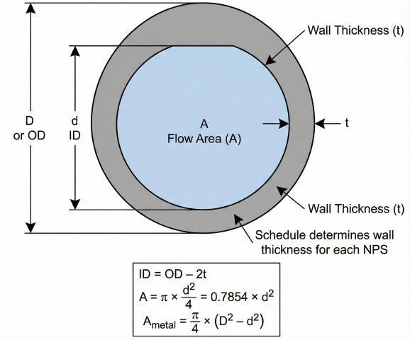
Inside Diameter
Metal Area (Pipe Wall)
Ovality Effect (Out-of-Roundness)
2. Velocity Relationships
Flow area connects volumetric flow rate to fluid velocity through the continuity equation.
Continuity Equation
Practical Velocity Formulas
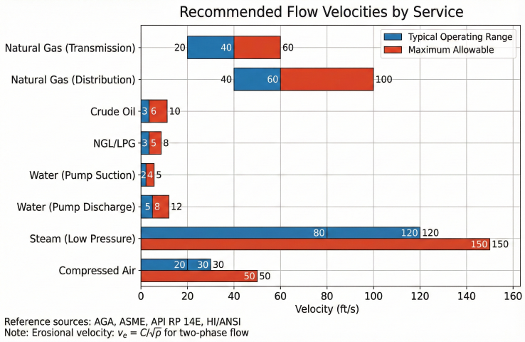
Recommended Velocities
| Service | Typical (ft/s) | Maximum (ft/s) | Reference |
|---|---|---|---|
| Natural gas (transmission) | 20–40 | 60 | AGA, ASME B31.8 |
| Natural gas (distribution) | 40–60 | 100 | ASME B31.8 |
| Crude oil | 3–6 | 10 | API RP 14E |
| NGL/LPG | 3–5 | 8 | GPSA |
| Water (pump suction) | 2–4 | 5 | HI/ANSI |
| Water (pump discharge) | 5–8 | 12 | HI/ANSI |
| Steam (low pressure) | 80–120 | 150 | ASME B31.1 |
| Compressed air | 20–30 | 50 | CAGI |
3. Reference Tables
Standard Pipe Flow Areas
| NPS | OD (in) | Schedule | Wall (in) | ID (in) | Area (in²) | Area (ft²) |
|---|---|---|---|---|---|---|
| 2" | 2.375 | 40 | 0.154 | 2.067 | 3.356 | 0.0233 |
| 4" | 4.500 | 40 | 0.237 | 4.026 | 12.73 | 0.0884 |
| 6" | 6.625 | 40 | 0.280 | 6.065 | 28.89 | 0.2006 |
| 8" | 8.625 | 40 | 0.322 | 7.981 | 50.03 | 0.3474 |
| 10" | 10.750 | 40 | 0.365 | 10.020 | 78.85 | 0.5476 |
| 12" | 12.750 | Std | 0.375 | 12.000 | 113.1 | 0.7854 |
| 16" | 16.000 | Std | 0.375 | 15.250 | 182.7 | 1.269 |
| 20" | 20.000 | Std | 0.375 | 19.250 | 291.0 | 2.021 |
| 24" | 24.000 | Std | 0.375 | 23.250 | 424.6 | 2.948 |
| 30" | 30.000 | Std | 0.375 | 29.250 | 672.0 | 4.666 |
| 36" | 36.000 | Std | 0.375 | 35.250 | 976.0 | 6.778 |
Area Ratios
4. Hydraulic Diameter
For non-circular cross-sections or partially filled pipes, hydraulic diameter relates flow area to wetted perimeter for use in friction factor correlations.
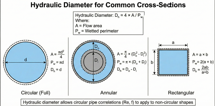
Definition
Common Cross-Sections
| Shape | Hydraulic Diameter |
|---|---|
| Circular (full) | D_h = d |
| Circular (half full) | D_h = d |
| Annulus | D_h = D_outer - D_inner |
| Square (side a) | D_h = a |
| Rectangle (a × b) | D_h = 2ab/(a+b) |
| Equilateral triangle | D_h = a/√3 |
Partially Filled Pipe
5. Applications
Reynolds Number
Line Sizing Example
Problem: Size a water line for 500 gpm at max 8 ft/s
Required area:
v = 0.4085 × Q / d²
8 = 0.4085 × 500 / d²
d² = 204.25 / 8 = 25.5
d = 5.05 inches minimum
Select 6" Sch 40:
ID = 6.065 in
v = 0.4085 × 500 / 6.065² = 5.55 ft/s ✓
Orifice and Restriction Areas
Common Uses
- Line sizing: Select pipe diameter for target velocity
- Pump selection: Calculate suction/discharge velocities
- Pressure drop: Velocity head = v²/2g
- Flow measurement: Orifice and venturi sizing
- Heat transfer: Convection coefficient correlations
- Erosion analysis: Check against erosional velocity limits
References
- ASME B36.10M – Welded and Seamless Wrought Steel Pipe (dimensions)
- API 5L – Specification for Line Pipe (tolerances, Table 10 ovality)
- ASTM A530 – General Requirements for Carbon Steel Pipe (tolerances)
- ASME B31.8 – Gas Transmission and Distribution Piping Systems
- API RP 14E – Design and Installation of Offshore Production Piping (erosional velocity)
- Crane TP-410 – Flow of Fluids Through Valves, Fittings, and Pipe
- GPSA
Ready to use the calculator?
→ Launch Calculator