The Taitel-Dukler correlation predicts flow patterns and pressure drop in horizontal gas-liquid pipelines. Essential for wet gas gathering systems, multiphase flowlines, and slug catcher design.
Two-phase flow occurs when gas and liquid flow simultaneously through a pipe. This is common in:
Wet gas pipelines - Natural gas with condensate or produced water
Oil gathering systems - Crude oil with associated gas
Well flowlines - Multiphase production from wellhead to separator
Process piping - Vapor-liquid streams in plants
The Taitel-Dukler methodology (1976) provides a mechanistic approach to predict flow patterns and calculate pressure drop in horizontal and near-horizontal pipes. It remains the industry standard for preliminary design.
Why Flow Pattern Matters
Flow Pattern
Pressure Drop
Operations Impact
Stratified
Lowest
Stable flow; corrosion risk at pipe bottom
Slug
Moderate-High
Pressure surges; separator upsets; vibration
Annular
High
Erosion risk; liquid mist carryover
Key References
Primary Sources:
1. Taitel, Y. and Dukler, A.E. (1976)
"A Model for Predicting Flow Regime Transitions in
Horizontal and Near Horizontal Gas-Liquid Flow"
AIChE Journal, Vol. 22, No. 1, pp. 47-55
2. Lockhart, R.W. and Martinelli, R.C. (1949)
"Proposed Correlation of Data for Isothermal Two-Phase,
Two-Component Flow in Pipes"
Chemical Engineering Progress, Vol. 45, pp. 39-48
3. Dukler, A.E. et al. (1964)
"Frictional Pressure Drop in Two-Phase Flow"
AIChE Journal, Vol. 10, No. 1, pp. 38-51
Industry Standard:
API RP 14E - Erosional velocity limits for two-phase flow
When to use Dukler vs. Beggs-Brill: Taitel-Dukler is best for horizontal and near-horizontal pipes (|angle| < 15°). For inclined or vertical pipes, use Beggs-Brill correlation which includes angle correction factors.
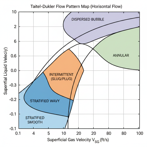
2. Flow Regime Map
The Taitel-Dukler flow pattern map uses dimensionless parameters to identify flow regime based on gas and liquid velocities, fluid properties, and pipe geometry.
Taitel-Dukler flow pattern map for horizontal two-phase flow showing regime transitions based on superficial velocities.
Flow Pattern Descriptions
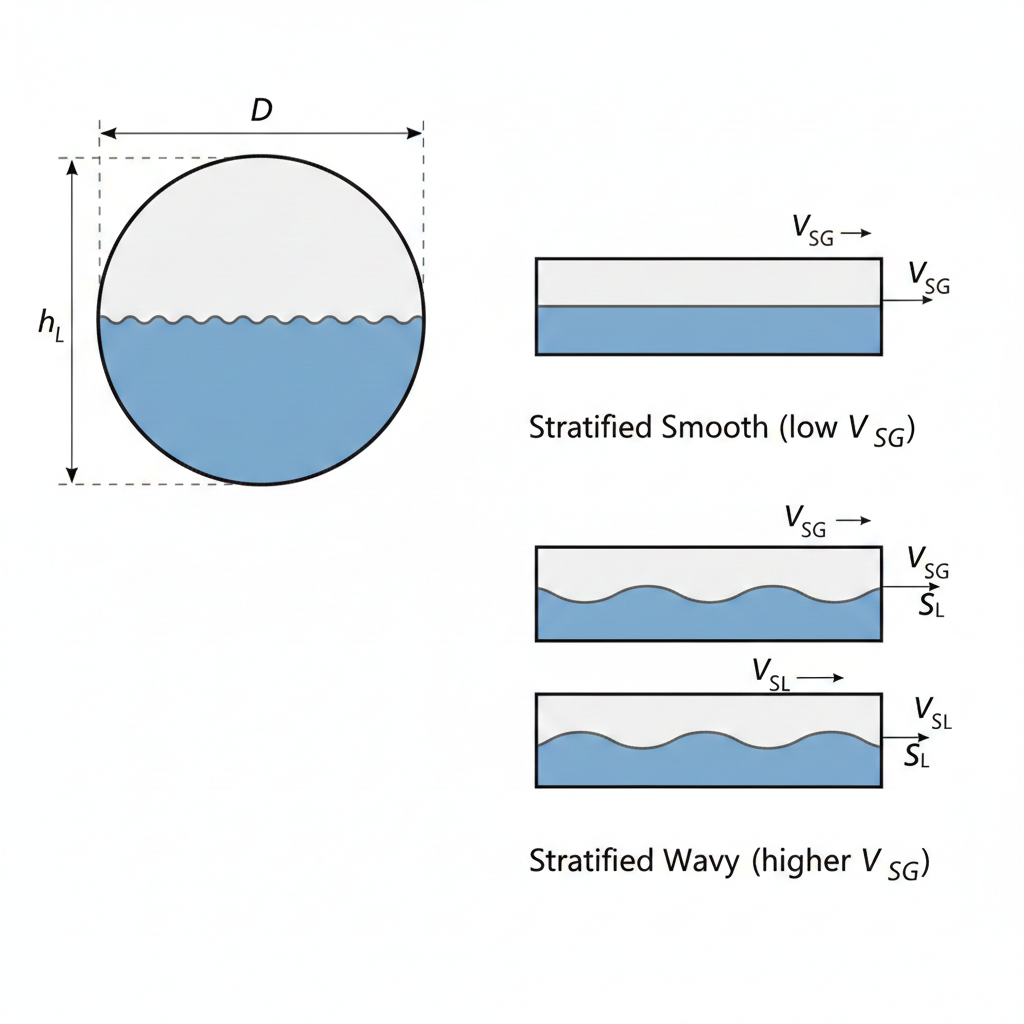
Stratified Flow (Smooth and Wavy)
Liquid flows at the bottom of the pipe with gas flowing above. At low gas velocities, the interface is smooth. As gas velocity increases, waves form on the liquid surface.
Stratified flow cross-section showing liquid accumulation at pipe bottom with smooth versus wavy interface comparison.
Conditions: Low gas velocity (<3-5 ft/s), low liquid rate
Holdup: HL = 0.1-0.5 (varies with pipe diameter and flow rates)
Pressure drop: Lowest of all regimes
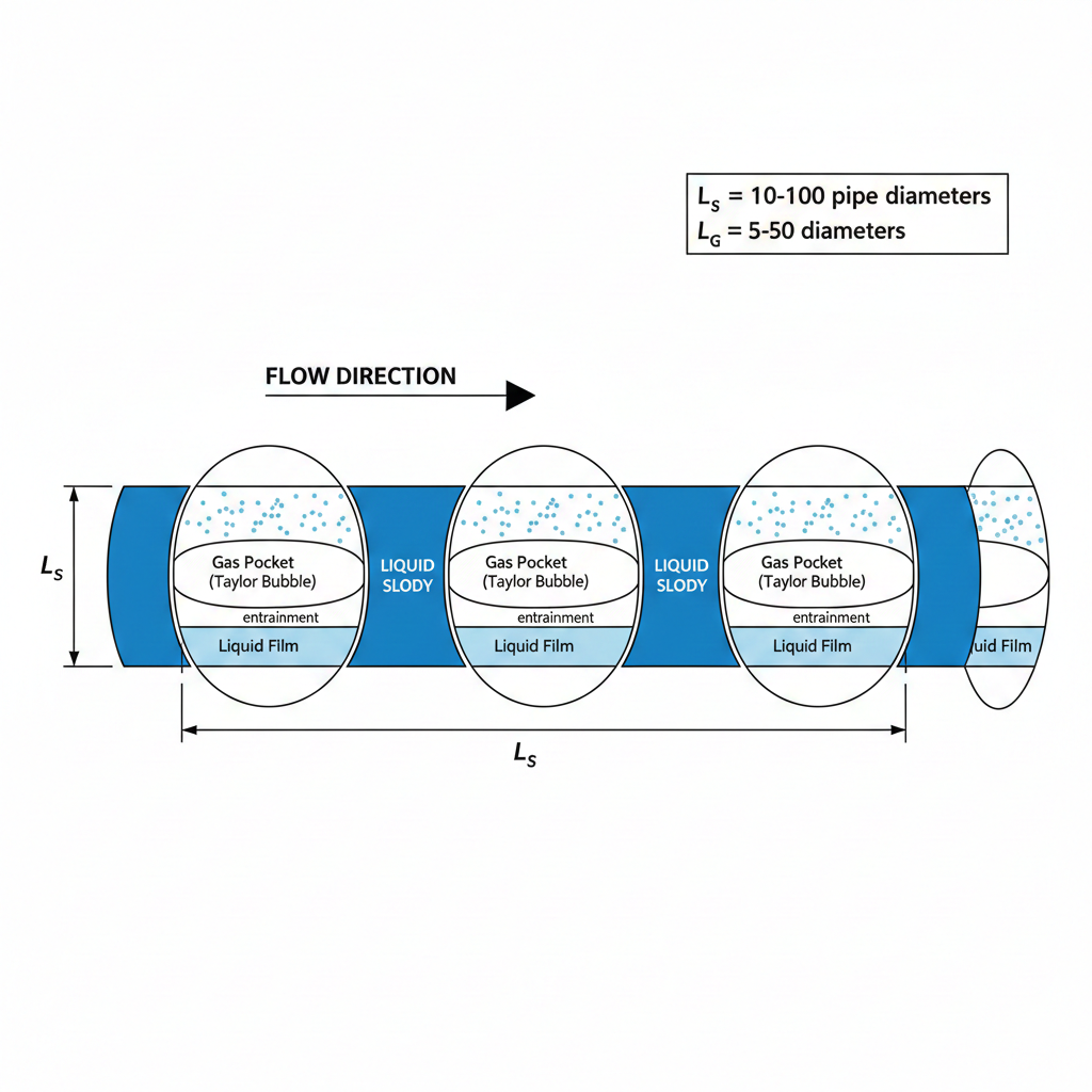
Intermittent Flow (Slug and Plug)
Liquid slugs periodically fill the entire pipe cross-section, alternating with gas pockets containing a liquid film at the bottom. This is the most problematic regime for operations.
Slug flow pattern showing alternating liquid slugs and gas pockets with characteristic length scales.
Conditions: Moderate gas velocity (5-20 ft/s), moderate liquid rate
Holdup: HL = 0.25-0.50 (time-averaged)
Problems: Pressure fluctuations, separator upsets, vibration, water hammer
Annular Flow
Liquid forms a thin film on the pipe wall while gas flows in the center. Some liquid is entrained as droplets in the gas core.
Conditions: High gas velocity (>20-30 ft/s), low-moderate liquid
Holdup: HL = 0.02-0.15 (thin film)
Considerations: Erosion risk if droplet velocity is high
Dispersed Bubble
Gas bubbles dispersed throughout continuous liquid phase. Rare in gas pipelines; more common in liquid-dominated systems.
Conditions: Very high liquid velocity, low gas fraction
Holdup: HL = 0.7-0.98
Flow Pattern Transition Criteria
Taitel-Dukler Transition Parameters:Stratified to Wavy:
Waves form when gas velocity creates interfacial shear exceeding
surface tension restoring force.
Transition occurs at:
K = FrG × √(ρG / Δρ) > 0.5
Where:
FrG = VSG / √(gD) (Gas Froude number)
Δρ = ρL - ρGWavy to Slug:
Waves grow large enough to bridge the pipe.
Occurs when liquid holdup allows waves to reach pipe top.
Transition at:
HL / D > 0.35 and K > 0.5
Slug to Annular:
High gas velocity strips liquid from slugs to wall film.
Transition at:
K > 3.5 and λL < 0.4
Where λL = VSL / (VSL + VSG)
Practical tip: In the field, flow pattern can often be identified by noise and vibration. Stratified flow is quiet. Slug flow produces rhythmic "thumping" or pressure surges. Annular flow has steady "hissing" sound from high-velocity gas.
3. Liquid Holdup
Liquid holdup (HL) is the fraction of pipe volume occupied by liquid at any instant. It determines mixture density, liquid inventory, and is critical for slug catcher sizing.
Holdup Definition:
HL = Vliquid / VpipeNo-Slip (Input) Liquid Fraction:
λL = QL / (QL + QG) = VSL / Vm
Where:
VSL = Superficial liquid velocity = QL / A
VSG = Superficial gas velocity = QG / A
Vm = Mixture velocity = VSL + VSGKey Relationship:
In most flow regimes: HL > λL
Liquid "holds up" (accumulates) because it moves slower than gas.
Ratio HL/λL is called the "slip ratio."
Holdup by Flow Regime
Flow Regime
Typical HL
Correlation Approach
Stratified Smooth
0.05-0.35
Mechanistic (momentum balance on each phase)
Stratified Wavy
0.10-0.40
Mechanistic with interfacial friction
Slug/Plug
0.20-0.55
Drift-flux model: HL = a×λLb/Frc
Annular
0.02-0.20
Film thickness correlation
Dispersed Bubble
0.70-0.98
Nearly no-slip: HL ≈ λL
Lockhart-Martinelli Parameter
The Lockhart-Martinelli parameter X relates single-phase pressure drops and is used in both holdup and pressure drop calculations.
Lockhart-Martinelli Parameter:
X = √[(dP/dL)L / (dP/dL)G]
Where:
(dP/dL)L = Pressure drop if only liquid flowed in pipe
(dP/dL)G = Pressure drop if only gas flowed in pipe
Calculation:
(dP/dL)L = fL × ρL × VSL² / (2D)
(dP/dL)G = fG × ρG × VSG² / (2D)
Where f is friction factor from Moody diagram.
Typical Values:
X < 0.1 → Gas-dominated (annular flow likely)
X = 0.1-1 → Transitional
X = 1-10 → Moderate two-phase
X > 10 → Liquid-dominated (bubble flow likely)
Liquid Inventory Calculation
Total liquid volume in pipeline is needed for pigging operations and slug catcher sizing.
Pipeline Liquid Inventory:
Vliquid = HL × Vpipe
Vpipe = π/4 × D² × L
Example:
Pipeline: 8-inch diameter, 10 miles long
HL = 0.30 (slug flow)
Vpipe = π/4 × (8/12)² × (10 × 5280) = 18,500 ft³
Vliquid = 0.30 × 18,500 = 5,550 ft³
= 5,550 / 5.615 = 988 barrels
This liquid must be handled by slug catcher during:
- Pigging operations (pig pushes all liquid ahead)
- Ramp-up or ramp-down transients
- Terrain-induced slugging
Design margin: For slug catcher sizing, add 50-100% margin to calculated liquid inventory to account for terrain effects and transient slugging. Final design should use transient simulation (OLGA or similar).
4. Two-Phase Pressure Drop
Two-phase pressure drop is significantly higher than single-phase due to liquid-gas interaction, increased friction, and density variations.
Pressure Drop Components
Total Pressure Gradient:
(dP/dL)total = (dP/dL)friction + (dP/dL)gravity + (dP/dL)acceleration1. Friction Component:
(dP/dL)f = (f × ρns × Vm²) / (2 × gc × D) × Φ²
Where:
Φ² = Two-phase multiplier (accounts for gas-liquid interaction)
ρns = No-slip mixture density = λL×ρL + (1-λL)×ρG
f = Darcy friction factor (from mixture Reynolds number)
gc = 32.174 lbm·ft/(lbf·s²)
2. Gravity Component:
(dP/dL)g = ρm × g × sin(θ)
ρm = In-situ mixture density = HL×ρL + (1-HL)×ρG
For horizontal pipe (θ = 0): This term = 0
3. Acceleration Component:
(dP/dL)a = ρm × Vm × dV/dL
Usually small for horizontal pipes; important for:
- High gas expansion (large pressure drop)
- Phase changes along pipe
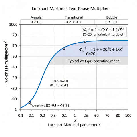
Lockhart-Martinelli Two-Phase Multiplier
The two-phase multiplier Φ² accounts for the increased pressure drop due to gas-liquid interaction.
Lockhart-Martinelli Correlation (1949):
ΦL² = 1 + C/X + 1/X²
Where C depends on flow regime of each phase:
┌─────────────────┬─────────────────┬───────┐
│ Liquid Flow │ Gas Flow │ C │
├─────────────────┼─────────────────┼───────┤
│ Turbulent │ Turbulent │ 20 │
│ Turbulent │ Laminar │ 12 │
│ Laminar │ Turbulent │ 10 │
│ Laminar │ Laminar │ 5 │
└─────────────────┴─────────────────┴───────┘
Turbulent: Re > 2300
Laminar: Re < 2300
Two-phase pressure drop:
(dP/dL)TP = (dP/dL)L-only × ΦL²
= (dP/dL)G-only × ΦG²
Example:
X = 0.5 (typical wet gas)
C = 20 (turbulent-turbulent)
ΦL² = 1 + 20/0.5 + 1/0.25 = 1 + 40 + 4 = 45
Pressure drop is 45× what liquid-only would be!
Or equivalently: (1 + 20×0.5 + 0.25) = 11.25× gas-only
Lockhart-Martinelli two-phase multiplier correlation showing pressure drop amplification factor.
Pressure Drop Comparison
Condition
dP/dL (psi/mile)
Relative
Gas only (no liquid)
5
1.0×
Stratified (HL=0.15)
10-15
2-3×
Slug flow (HL=0.35)
20-40
4-8×
Annular (HL=0.10)
25-50
5-10×
Design impact: Even small amounts of liquid (1-5 bbl/MMscf) can double or triple pressure drop compared to dry gas. Always check for liquid content in "wet gas" pipelines and account for two-phase effects in hydraulic design.
5. Design Applications
Erosional Velocity (API RP 14E)
Maximum allowable velocity to prevent pipe wall erosion from liquid droplet impact.
API RP 14E Erosional Velocity:
Ve = C / √ρm
Where:
Ve = Erosional velocity (ft/s)
ρm = Mixture density (lb/ft³)
C = Empirical constant
C Factor Guidelines:
C = 100 Continuous service, corrosive, solids present
C = 125 Intermittent service, clean fluids
C = 150 Non-corrosive, no solids, controlled conditions
C = 200 Theoretical maximum (rarely used)
Example:
ρm = 15 lb/ft³ (typical wet gas)
C = 100 (conservative)
Ve = 100 / √15 = 25.8 ft/s
If Vm > 25.8 ft/s → Increase pipe diameter
Slug Catcher Sizing
Slug catchers buffer liquid surges from pipelines before separators.
Slug Catcher Volume:
VSC = Vslug-max + Vsurge + VholdupComponents:
Vslug-max = Maximum single slug volume
Vsurge = Ramp-up liquid surge (typically 50% of inventory)
Vholdup = Normal operating holdup (10-20 minutes residence)
Slug Volume Estimate:
Vslug = HL-slug × A × Lslug
Where:
HL-slug ≈ 0.5-0.7 (slug body holdup)
Lslug = Slug length (can be 100-5000 ft)
Rule of Thumb:
For preliminary sizing:
VSC = 1.5 × (Pipeline liquid inventory)
Final sizing requires transient simulation.
Design Checklist
Step 1
Determine Flow Rates
Gas and liquid at operating P, T. Include maximum, minimum, and normal cases.
Step 2
Predict Flow Pattern
Use Taitel-Dukler map. Identify if slug flow is possible.
Step 3
Calculate Holdup
Determine liquid inventory for pigging and slug catcher.
Step 4
Pressure Drop
Segment pipeline. Iterate for compressibility.
Step 5
Check Erosion
Verify Vm < Ve per API RP 14E.
Step 6
Validate with Simulation
Use OLGA/PIPESIM for final design and transient analysis.
Common Mistakes to Avoid
Ignoring liquid: Treating wet gas as dry gas under-predicts pressure drop by 2-10×
Wrong correlation: Using Dukler for vertical flow (use Beggs-Brill) or vice versa
Neglecting terrain: Elevation changes cause liquid accumulation and terrain slugging
Undersizing slug catcher: Leads to separator trips and production losses
No erosion check: Pipe thinning failures from exceeding erosional velocity
Steady-state only: Missing transient slugging during startup/shutdown
Best practice: For pipelines with liquid content >5 bbl/MMscf, always perform two-phase analysis. Use Taitel-Dukler for preliminary design, validate with commercial multiphase simulator (OLGA, PIPESIM, PIPEPHASE) for final design.
What are the five flow regimes predicted by the Taitel-Dukler model?+
The five flow regimes are stratified smooth, stratified wavy, intermittent (slug and plug), annular, and dispersed bubble. The model uses mechanistic transition criteria based on fundamental fluid mechanics rather than purely empirical correlations.
What is the Lockhart-Martinelli parameter used for in two-phase flow?+
The Lockhart-Martinelli parameter X relates single-phase liquid and gas pressure gradients and is used to predict two-phase pressure drop multiplier and liquid holdup. Typical two-phase pressure drop multipliers range from 2–20 times the single-phase gas value.
When should you use the Taitel-Dukler model versus Beggs-Brill?+
Taitel-Dukler is preferred for horizontal and near-horizontal pipelines where flow regime prediction accuracy is critical, such as slug catcher design. Beggs-Brill is better for inclined pipelines with varying terrain since it handles all inclination angles.