Tensile Strength: ASTM Material Engineering Fundamentals
Calculate tensile strength, yield strength, and ultimate tensile strength for pipeline materials using ASTM A370 testing methods and API 5L material grades.
Select appropriate material grade for service conditions.
Interpret tensile test results per ASTM A370.
1. Overview & Applications
Tensile strength is the maximum stress a material can withstand while being stretched or pulled before breaking. For pipeline design, both yield strength and ultimate tensile strength are critical properties that determine allowable operating pressures and safety factors.
Pipeline design
Pressure calculations
SMYS determines MAOP per Barlow's equation and ASME B31.8.
Material selection
Grade specification
API 5L grades (X42-X80) selected based on pressure, diameter, location class.
Integrity assessment
Defect evaluation
Tensile properties used in fitness-for-service and remaining strength calculations.
Weld qualification
Strength matching
Weld metal must meet or exceed base metal tensile properties per API 1104.
Key Definitions
Yield Strength (YS): Stress at which permanent plastic deformation begins (0.2% offset method)
Specified Minimum Yield Strength (SMYS): Minimum guaranteed yield strength for material grade
Ultimate Tensile Strength (UTS): Maximum stress material can withstand before fracture
Elongation: Percentage increase in length at fracture (ductility measure)
Modulus of Elasticity (E): Slope of stress-strain curve in elastic region (29×10⁶ psi for steel)
Design philosophy: Pipeline codes use SMYS as the design basis, not actual yield strength. This provides built-in safety margin since actual material typically exceeds SMYS by 5-15 ksi. ASME B31.8 limits operating stress to 72% SMYS (0.72 design factor for Class 1 locations).
Relationship Between Properties
For carbon steel pipeline materials:
UTS/YS ratio typically 1.4 to 1.6 (material must show work hardening)
Elongation typically 18-25% for grades X42-X70
Higher strength grades (X70-X80) may have lower elongation (15-20%)
Charpy impact toughness inversely related to strength for given steel chemistry
2. Stress-Strain Behavior
The stress-strain curve describes material behavior under tensile loading and reveals key mechanical properties used in design.
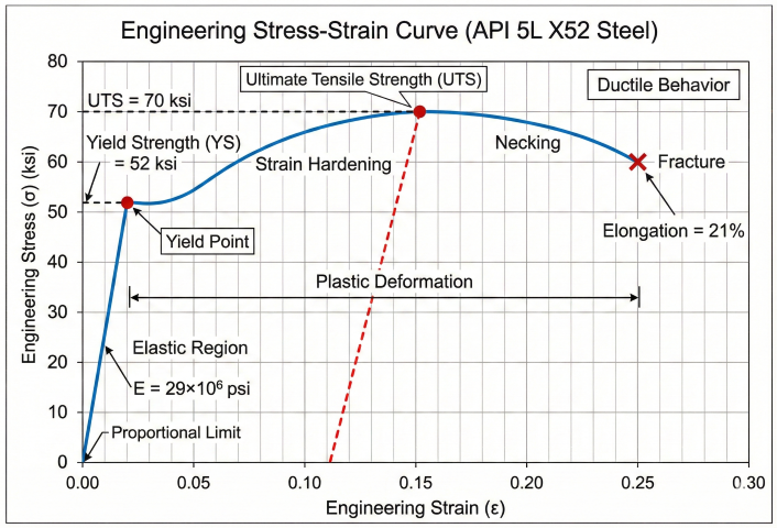
Engineering Stress-Strain Curve for API 5L X52 Steel: Shows elastic region, yield point (52 ksi), strain hardening to UTS (70 ksi), necking, and fracture with 21% elongation.
Fundamental Stress-Strain Relationship
Stress and Strain Definitions:
Engineering Stress:
σ = F / A₀
Where:
σ = Engineering stress (psi or MPa)
F = Applied force (lb or N)
A₀ = Original cross-sectional area (in² or mm²)
Engineering Strain:
ε = (L - L₀) / L₀ = ΔL / L₀
Where:
ε = Engineering strain (dimensionless or %)
L = Current length
L₀ = Original length
ΔL = Change in length
Elastic Region (Hooke's Law):
σ = E × ε
Where:
E = Modulus of elasticity (Young's modulus)
E = 29×10⁶ psi for carbon steel
E = 200 GPa for carbon steel
Regions of Stress-Strain Curve
Region
Behavior
Key Point
Design Relevance
Elastic region
Linear, reversible
Proportional limit
Normal operating range (0-72% SMYS)
Yield point
Onset of plastic deformation
0.2% offset yield strength
Design basis (SMYS) for pipeline codes
Strain hardening
Plastic deformation, increasing stress
Work hardening
Reserve capacity beyond yield
Ultimate strength
Maximum stress
UTS (tensile strength)
Failure limit for burst pressure
Necking
Localized thinning
Reduction of area begins
Precursor to fracture
Fracture
Material separation
Breaking strength
Ultimate failure mode
0.2% Offset Yield Strength Method
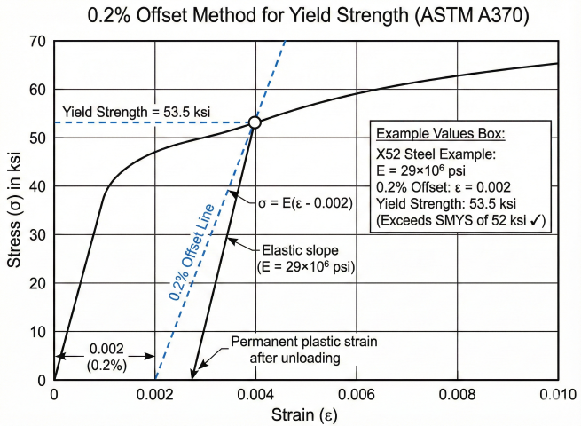
0.2% Offset Yield Strength Method (ASTM A370): Parallel line offset by 0.002 strain intersects curve at yield strength. Example shows X52 steel with YS = 53.5 ksi (exceeds 52 ksi SMYS).
Determining Yield Strength (ASTM E8/A370):
Many steels do not exhibit a sharp yield point. The 0.2% offset method
provides a standardized definition:
1. Plot stress-strain curve from tensile test
2. Draw a line parallel to elastic region, offset by 0.2% strain (ε = 0.002)
3. Intersection with stress-strain curve defines yield strength
Offset line equation:
σ = E × (ε - 0.002)
For steel with E = 29×10⁶ psi:
σ_offset = 29×10⁶ × (ε - 0.002)
The 0.2% offset corresponds to permanent plastic strain after unloading.
This method ensures consistent, repeatable yield strength determination.
True Stress and True Strain
True Stress-Strain (Instantaneous Area):
Engineering stress uses original area A₀, but specimen necks during testing.
True stress uses instantaneous area:
True Stress:
σ_true = F / A_instantaneous
True Strain:
ε_true = ln(L / L₀) = ln(1 + ε_eng)
Relationship to engineering values:
σ_true = σ_eng × (1 + ε_eng)
ε_true = ln(1 + ε_eng)
True stress-strain better represents material behavior in plastic region
but is not used for design specifications. SMYS and UTS use engineering stress.
Typical Steel Stress-Strain Values
Material Grade
SMYS (psi)
SMTS (psi)
Elongation (%)
SMTS/SMYS Ratio
API 5L Grade B
35,500
60,200
22
1.70
API 5L X42
42,100
60,200
22
1.43
API 5L X52
52,200
66,700
21
1.28
API 5L X60
60,200
75,400
20
1.25
API 5L X65
65,300
77,600
19
1.19
API 5L X70
70,300
82,700
18
1.18
API 5L X80
80,500
90,600
17
1.13
Values per API 5L 46th Edition, Tables 4 and 7. SMTS = Specified Minimum Tensile Strength.
Ductility requirement: Pipeline specifications require minimum elongation to ensure ductile behavior. API 5L requires elongation ≥ 18% for grades through X65, and ≥ 17% for X70-X80. Brittle materials with low elongation are unsuitable for pipeline service due to crack propagation risk.
Factors Affecting Tensile Properties
Microstructure: Grain size, phase composition (ferrite/pearlite/bainite) affect strength and toughness
Chemical composition: Carbon, manganese, niobium, vanadium increase strength through solid solution or precipitation hardening
Temperature: Strength decreases with increasing temperature; ductility increases
Cold work: Prior deformation increases yield strength but reduces ductility
Heat treatment: Quenching and tempering, normalizing affect final properties
3. API 5L Material Grades
API 5L "Specification for Line Pipe" defines standardized grades for oil and gas pipeline materials. Grade designation (X42, X52, etc.) indicates SMYS in ksi.
API 5L Grade Specifications
Grade Designation System:
API 5L Grade X[number]
Where [number] = SMYS in ksi
Example: API 5L Grade X52
- SMYS = 52,000 psi (52 ksi)
- Minimum UTS = 66,000 psi (66 ksi)
- Material must meet both strength and toughness requirements
PSL (Product Specification Level):
- PSL 1: Standard requirements for line pipe
- PSL 2: Enhanced requirements (tighter chemistry, mandatory Charpy testing)
Delivery Condition:
- As-rolled
- Normalized
- Thermomechanically rolled
- Quenched and tempered
Complete API 5L Grade Table
Grade
SMYS (psi)
SMYS (MPa)
Min. UTS (psi)
Min. UTS (MPa)
Typical Application
Grade A
30,500
210
48,600
335
Low-pressure, older lines
Grade B
35,500
245
60,200
415
Distribution, gathering
X42
42,100
290
60,200
415
Low-pressure transmission
X46
46,400
320
63,100
435
Intermediate service
X52
52,200
360
66,700
460
Transmission pipelines
X56
56,600
390
71,100
490
High-pressure transmission
X60
60,200
415
75,400
520
High-pressure transmission
X65
65,300
450
77,600
535
High-pressure, large diameter
X70
70,300
485
82,700
570
High-pressure trunk lines
X80
80,500
555
90,600
625
Ultra-high pressure, Arctic
X90
90,600
625
100,800
695
Special high-pressure projects
X100
100,800
690
110,200
760
Emerging, limited use
Chemical Composition Requirements
API 5L PSL 2 specifies maximum carbon equivalent to ensure weldability:
Carbon Equivalent (CE) Formulas:
International Institute of Welding (IIW) formula:
CE_IIW = C + Mn/6 + (Cr + Mo + V)/5 + (Ni + Cu)/15
Petroleum and Chemical Industry (Pcm) formula:
CE_Pcm = C + Si/30 + (Mn + Cu + Cr)/20 + Ni/60 + Mo/15 + V/10 + 5B
Where all elements in weight %
API 5L PSL 2 Limits:
- CE_IIW ≤ 0.43% for grades ≤ X70
- CE_Pcm ≤ 0.25% for grades ≤ X70
- Lower CE ensures good weldability (reduced crack susceptibility)
Typical X52 Composition:
C: 0.26% max
Mn: 1.40% max
P: 0.025% max
S: 0.015% max
Toughness Requirements
API 5L PSL 2 mandates Charpy V-notch impact testing to ensure adequate toughness:
Grade
Min. Charpy Energy (J)
Test Temperature
Purpose
X42-X52
27 (average of 3)
0°C (32°F)
Ductile fracture resistance
X56-X65
27 (average of 3)
0°C or -10°C
Prevent brittle fracture
X70-X80
40 (average of 3)
-10°C or -20°C
Crack arrest capability
Sour service (X42-X65)
40 minimum average
Per NACE MR0175
Sulfide stress cracking resistance
Grade selection strategy: Higher grades (X70, X80) enable higher operating pressures or reduced wall thickness, lowering material costs for large-diameter lines. However, they require more stringent welding procedures, heat input control, and quality assurance. Economic analysis must balance material savings against construction complexity.
4. ASTM A370 Testing Methods
ASTM A370 "Standard Test Methods and Definitions for Mechanical Testing of Steel Products" defines procedures for determining tensile properties of pipeline materials.
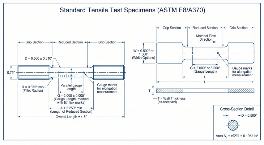
Standard Tensile Test Specimens (ASTM E8/A370): Round specimen (0.500" dia, 2.000" gauge) and flat specimen from pipe body with standard dimensions for mechanical testing.
Extensometer attachment: Attach strain gauge or extensometer to measure elongation
Preload: Apply small preload to seat specimen, zero load and strain readings
Loading: Apply tension at specified strain rate, record load and elongation continuously
Yield determination: Identify yield point or apply 0.2% offset method
Ultimate load: Continue loading until maximum load (UTS) is reached
Fracture: Load specimen to fracture, note final load
Elongation measurement: Fit broken pieces together, measure final gauge length
Area measurement: Measure minimum cross-section at fracture (reduction of area)
Calculated Properties from Test
Tensile Test Calculations:
Yield Strength (0.2% offset):
YS = P_y / A₀
Where:
P_y = Load at 0.2% offset intersection (lb)
A₀ = Original cross-section area (in²)
Ultimate Tensile Strength:
UTS = P_max / A₀
Where:
P_max = Maximum load during test (lb)
Percent Elongation:
%EL = [(L_f - L₀) / L₀] × 100%
Where:
L_f = Final gauge length after fracture (in)
L₀ = Original gauge length (in)
Percent Reduction of Area:
%RA = [(A₀ - A_f) / A₀] × 100%
Where:
A_f = Final minimum cross-section area at fracture (in²)
Example Calculation:
Original diameter: D₀ = 0.500 in → A₀ = 0.1963 in²
Yield load: P_y = 10,500 lb
Maximum load: P_max = 14,800 lb
Original gauge: L₀ = 2.00 in
Final gauge: L_f = 2.42 in
Final diameter: D_f = 0.385 in → A_f = 0.1164 in²
YS = 10,500 / 0.1963 = 53,490 psi (53.5 ksi)
UTS = 14,800 / 0.1963 = 75,395 psi (75.4 ksi)
%EL = (2.42 - 2.00) / 2.00 × 100% = 21%
%RA = (0.1963 - 0.1164) / 0.1963 × 100% = 40.7%
Material meets X52 requirements (SMYS 52 ksi, UTS 66 ksi minimum)
Specimen Location and Orientation
Specimen Type
Location
Orientation
Purpose
Longitudinal
Pipe body
Parallel to pipe axis
Hoop stress direction (primary)
Transverse
Pipe body
Perpendicular to pipe axis
Longitudinal stress properties
All-weld metal
Across weld
Perpendicular to weld
Weld metal strength verification
Weld cross-section
Includes weld + HAZ + base
Perpendicular to weld
Weakest link identification
Acceptance Criteria
API 5L and project specifications define acceptance criteria for tensile testing:
Yield strength: Must meet or exceed SMYS for specified grade
Tensile strength: Must meet minimum UTS for grade; typical maximum limit is SMYS + 15 ksi
Yield-to-tensile ratio: UTS/YS typically ≥ 1.1 (API 5L PSL 2: depends on grade)
Elongation: Must meet minimum for grade (typically 18-22%)
Weld specimens: Must meet or exceed base metal properties (or 95% minimum per some codes)
Testing frequency: API 5L requires tensile testing per heat of steel (melt batch). For production pipe, typically one test per 200-500 feet of pipe. Welding procedure qualification requires a coupon set per API 1104 Table 3 that scales with pipe OD and wall: 2 nick-break + 2 bend for OD ≤ 4½″ (tensile added only if grade > X42), 2 tensile + 2 nick-break + 4 bend for >4½–12¾″, and 4 tensile + 4 nick-break + 8 bend for OD > 12¾″. Welder qualification and destructive testing of production welds (Table 7) take no tensile — nick-break + bends only. Production weld testing frequency is per ASME B31.8 or project requirements (often 10-20% of welds).
Common Testing Issues
Premature fracture in grips: Indicates inadequate grip pressure or grip section too short—test invalid
Fracture outside gauge length: Test invalid per ASTM A370; elongation cannot be measured accurately
Strain rate too fast: Artificially increases apparent yield strength—test invalid
Temperature effects: Test at non-standard temperature requires temperature correction factors
5. Design Applications
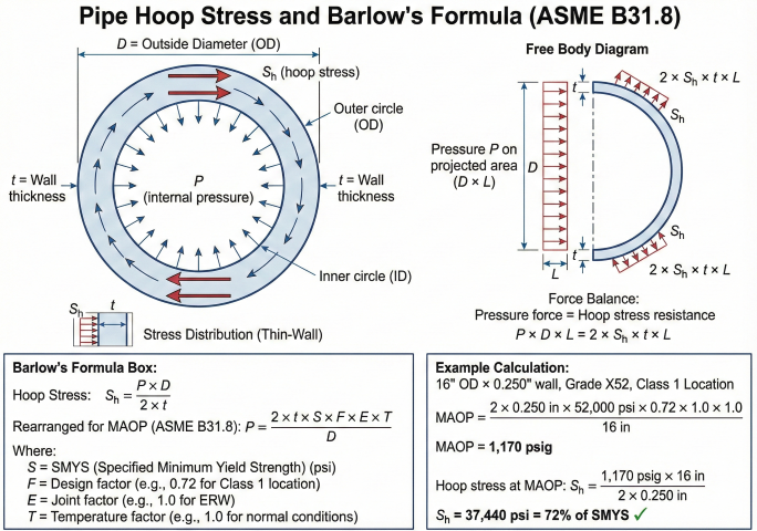
Pipe Hoop Stress and Barlow's Formula (ASME B31.8): Internal pressure creates hoop stress Sh = PD/2t. Example shows MAOP calculation for 16" OD × 0.250" wall X52 pipe = 1,170 psig.
Barlow's Formula for Pipeline Pressure
Barlow's formula relates hoop stress to internal pressure using SMYS as design basis:
Barlow's Equation (Thin-Wall Approximation):
Hoop Stress:
S_h = (P × D) / (2 × t)
Maximum Allowable Operating Pressure (MAOP):
P = (2 × t × SMYS × F × E × T) / D
Where:
P = Internal pressure (psig)
t = Pipe wall thickness (inches)
D = Outside diameter (inches)
SMYS = Specified Minimum Yield Strength (psi)
F = Design factor (0.72 for Class 1, 0.60 for Class 3, per B31.8)
E = Longitudinal joint factor (1.0 for seamless or ERW, 0.8 for furnace butt weld)
T = Temperature derating factor (1.0 for T ≤ 250°F)
Example: 16" OD, X52 pipe, 0.250" wall, Class 1 location
MAOP = (2 × 0.250 × 52,000 × 0.72 × 1.0 × 1.0) / 16
MAOP = 18,720 / 16 = 1170 psig
Hoop stress at MAOP:
S_h = (1170 × 16) / (2 × 0.250) = 37,440 psi = 72% SMYS ✓
Design Factor Selection (ASME B31.8)
Location Class
Building Density
Design Factor (F)
% SMYS
Class 1, Division 1
0-10 buildings per mi²
0.80
80%
Class 1, Division 2
10-46 buildings per mi²
0.72
72%
Class 2
46-200 buildings per mi²
0.60
60%
Class 3
>200 buildings per mi²
0.50
50%
Class 4
High-rise buildings
0.40
40%
Wall Thickness Calculation
Required Wall Thickness (ASME B31.8):
Rearranging Barlow's formula for thickness:
t = (P × D) / (2 × SMYS × F × E × T)
Add corrosion allowance:
t_required = t_pressure + CA
Add manufacturing tolerance:
t_nominal = t_required / (1 - tolerance)
Tolerance = 12.5% typical (t_min = 87.5% t_nominal)
Example: Design for 1200 psig, 20" OD, X65 pipe, Class 2
t_pressure = (1200 × 20) / (2 × 65,000 × 0.60 × 1.0 × 1.0)
t_pressure = 24,000 / 78,000 = 0.308 inches
With CA = 0.062" (1/16"):
t_required = 0.308 + 0.062 = 0.370 inches
With 12.5% tolerance:
t_nominal = 0.370 / 0.875 = 0.423 inches
Select next standard: 0.438" (7/16") or 0.500" (1/2")
Burst Pressure Calculation
Theoretical Burst Pressure:
Using UTS instead of SMYS (no design factor):
P_burst = (2 × t × UTS) / D
For X52 pipe: UTS = 66,000 psi minimum
For 16" OD × 0.250" wall:
P_burst = (2 × 0.250 × 66,000) / 16 = 2062 psig
Actual burst may be 90-95% of theoretical due to:
- Material scatter (some locations below average UTS)
- Geometric imperfections (ovality, wall thinning)
- Stress concentrations (welds, dents)
- Strain hardening effects in thin-wall pipe
Safety margin:
MAOP = 1170 psig
Burst = 2062 psig (theoretical)
Safety factor = 2062 / 1170 = 1.76
This margin protects against pressure surges, material variations, and defects.
Material Grade Selection Example
Select appropriate grade for 24" OD pipeline, 1440 psig MAOP, Class 1 (F=0.72):
Grade Selection Process:
Step 1: Assume wall thickness (try 0.375"):
Required SMYS = (P × D) / (2 × t × F × E × T)
Required SMYS = (1440 × 24) / (2 × 0.375 × 0.72 × 1.0 × 1.0)
Required SMYS = 34,560 / 0.540 = 64,000 psi
Conclusion: Need grade with SMYS ≥ 64 ksi → X65 (65 ksi) or X70 (70 ksi)
Step 2: Check with X65:
MAOP_X65 = (2 × 0.375 × 65,000 × 0.72 × 1.0 × 1.0) / 24
MAOP_X65 = 35,100 / 24 = 1462 psig ✓ (exceeds 1440 psig requirement)
Step 3: Alternative with X52 (thicker wall):
Required t = (1440 × 24) / (2 × 52,000 × 0.72 × 1.0 × 1.0)
Required t = 34,560 / 74,880 = 0.461 inches
Select nominal: 0.500" wall
Step 4: Economic comparison:
Option A: X65 @ 0.375" wall = 24" × 0.375" × 490 lb/ft² = 4.41 lb/ft
Option B: X52 @ 0.500" wall = 24" × 0.500" × 490 lb/ft² = 5.89 lb/ft
Weight savings: (5.89 - 4.41) / 5.89 = 25% lighter with X65
For 100-mile pipeline:
X65: 4.41 lb/ft × 5280 ft/mi × 100 mi = 2.33 million lb
X52: 5.89 lb/ft × 5280 ft/mi × 100 mi = 3.11 million lb
Material savings: 780,000 lb (390 tons)
At $1000/ton, material cost savings = $390,000
However, X65 costs ~15% more per pound than X52, and requires stricter
welding procedures. Full economic analysis required.
Fitness-for-Service Assessment
Tensile properties are used to evaluate defect acceptability per API 579/ASME FFS-1:
Remaining strength factor (RSF): Ratio of reduced cross-section strength to original strength
Corrosion metal loss: Calculate remaining wall thickness, compare stress to SMYS × F
Crack-like flaws: Use fracture mechanics with UTS and Charpy toughness to determine critical crack size
Dents and mechanical damage: Assess peak stress concentration factor, compare to yield strength
Hard spots: Local high hardness indicates high yield strength but low toughness—evaluate cracking risk
Pressure test requirements: ASME B31.8 requires hydrostatic testing to 1.5 × MAOP (Class 1) or 1.25 × MAOP (Class 3, 4). Test stress should remain below 100% SMYS to avoid overstrain. For high test factors, may require strength test (spike test) at 1.25-1.4 × MAOP, held briefly, followed by standard test at 1.1 × MAOP for leak detection.
Common Design Errors
Using actual yield strength instead of SMYS: SMYS is the design basis; actual YS provides safety margin
Neglecting joint factor (E): ERW pipe prior to 1970 may have E = 0.8, reducing allowable pressure by 20%
Ignoring corrosion allowance: Must add CA to pressure-required thickness before selecting nominal wall
Confusing OD and ID in Barlow's formula: Use outside diameter (OD) for thin-wall approximation
Using gauge pressure with absolute formulas: Barlow's formula uses gauge pressure; gas law requires absolute
What is the difference between SMYS and UTS in pipeline design?+
SMYS (Specified Minimum Yield Strength) is the design basis for pipeline pressure calculations per ASME B31.8, representing the stress at which permanent deformation begins. UTS (Ultimate Tensile Strength) is the maximum stress before fracture and is used in defect evaluation and remaining strength assessments.
How is yield strength measured using the 0.2% offset method?+
A line is drawn parallel to the elastic portion of the stress-strain curve, offset by 0.2% strain. The intersection of this line with the actual stress-strain curve defines the yield strength. This method is standard per ASTM A370 for materials without a distinct yield point.
What are the API 5L pipeline steel grades and their yield strengths?+
API 5L grades range from X42 (42,000 psi SMYS) through X80 (80,000 psi SMYS). The grade designation number directly indicates the minimum yield strength in ksi. X52 is the most common transmission pipeline grade.