Pressure Relief Systems

Flare Disposal System Design

Design flare headers and knockout drums using API RP 521 methodology. Ensure safe disposal of relief loads while maintaining acceptable Mach numbers and vapor-liquid separation.

Header Mach limit

≤ 0.5 (recommended)

API RP 521 limits Mach to 0.7 max; 0.5 preferred for acoustic fatigue prevention.

K-value range

0.10 - 0.35

Souders-Brown K-values vary by service: dry gas (0.35) to foaming (0.10).

Governing standard

API RP 521

7th Edition: Pressure-Relieving and Depressuring Systems.

Use this guide when you need to:

  • Size flare headers for relief loads
  • Design knockout drums for liquid separation
  • Verify Mach number and velocity limits

1. System Overview

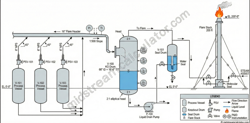
Flare disposal systems safely collect, transport, and combust relief discharges from pressure safety valves (PSVs), blowdown valves, and emergency depressuring systems. The system must handle transient high-flow events while maintaining acceptable backpressure on relief devices.

Flare header

Collect & transport

Routes relief gases from multiple sources to the flare stack or ground flare.

Knockout drum

Liquid separation

Removes entrained liquids before combustion to prevent liquid carryover to flare tip.

Liquid seal drum

Flashback prevention

Water seal prevents flame propagation back into the header system.

Flare stack/tip

Combustion

Elevated or ground-level combustion with proper radiation protection.

Flare disposal system P&ID showing PSVs, header, KO drum, seal drum, and flare stack.

Key Design Criteria

  • Backpressure limit: Total backpressure at PSV outlet must not exceed allowable (typically 10% of set pressure for conventional valves)
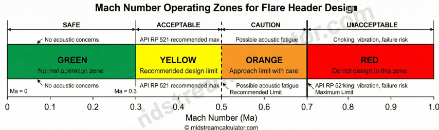
  • Mach number: Velocity must remain below sonic to prevent choking and acoustic fatigue
  • Liquid separation: KO drum must capture entrained liquids to protect flare tip and prevent liquid rainout
  • Seal integrity: Liquid seal must prevent flashback under all operating conditions
Critical design consideration: Flare header sizing is governed by two competing constraints: (1) Mach number limit to prevent acoustic fatigue and sonic choking, and (2) pressure drop limit to maintain acceptable PSV backpressure. Both must be checked for the design relief scenario.

Typical Relief Scenarios

Scenario Duration Flow Character Design Consideration
Fire case Extended (hours) Steady, vapor Simultaneous relief from fire-exposed vessels
Power failure Minutes Peak then decay Loss of cooling/compression across plant
Blocked outlet Minutes Steady, single source Usually single PSV, check header routing
Emergency depressuring 15-20 min High initial, decaying Largest single relief load typically
Tube rupture Minutes Steady, two-phase High liquid fraction possible

3. Knockout Drum Sizing

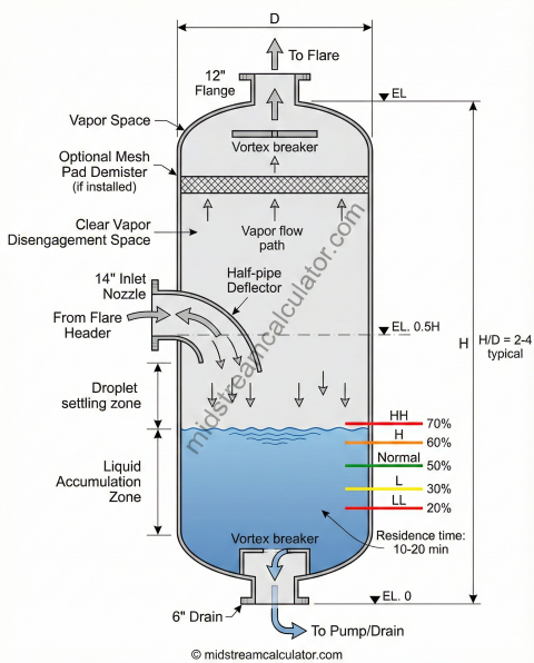
Knockout drums (KO drums) separate entrained liquid droplets from the vapor stream before the flare tip. Proper sizing prevents liquid carryover (burning liquid rain) and ensures adequate liquid storage capacity.

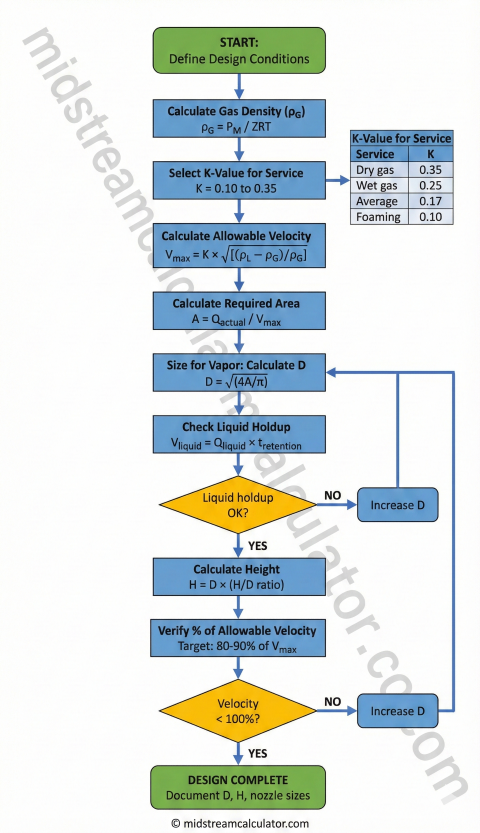
Souders-Brown Vapor Velocity

Maximum Allowable Vapor Velocity: V_max = K × √[(ρL - ρG) / ρG] Where: V_max = Maximum vapor velocity (ft/s) K = Souders-Brown coefficient (ft/s) ρL = Liquid density (lb/ft³) ρG = Gas density (lb/ft³) The K-value depends on: • Droplet size distribution • Vessel internals (mesh pad, vanes) • Foaming tendency • Operating pressure API RP 521 K-Values (vertical drums, no internals): | Service Type | K (ft/s) | Application | |--------------|----------|-------------| | Dry gas | 0.35 | Clean gas, no liquid expected | | Wet gas | 0.25 | Some liquid, light hydrocarbon | | Average | 0.17 | Typical oilfield gas with condensate | | Dirty/foaming | 0.125 | High liquid, surfactants present | | Glycol/amine | 0.10 | Foaming chemical services | With mesh pad demister: K can increase 50-100% With vane pack: K can increase 20-40%
Vertical knockout drum cross-section with internals and level instruments.

Drum Diameter Sizing

Required Diameter from Vapor Velocity: A_req = Q_actual / V_max D = √(4 × A_req / π) Where: A_req = Required cross-sectional area (ft²) Q_actual = Actual volumetric flow rate (ft³/s) V_max = Maximum allowable velocity (ft/s) D = Drum diameter (ft) Actual Volumetric Flow: Q_actual = W_gas / (ρG × 3600) Where: W_gas = Gas mass flow rate (lb/hr) ρG = Gas density at operating conditions (lb/ft³) Gas Density: ρG = P × M / (Z × R × T) Where: P = Absolute pressure (psia) M = Molecular weight Z = Compressibility factor R = 10.73 psia-ft³/(lbmol-°R) T = Absolute temperature (°R)

Liquid Holdup and Height

Liquid Holdup Volume: V_liquid = Q_liquid × t_retention Where: V_liquid = Liquid holdup volume (ft³) Q_liquid = Liquid volumetric flow rate (ft³/min) t_retention = Retention time (minutes) Typical Retention Times: | Application | Retention (min) | |-------------|-----------------| | Emergency KO drum | 10-20 | | Normal service | 5-10 | | High liquid rate | 15-30 | | Intermittent service | 5 | Drum Height (Vertical): For vertical drums, use Height/Diameter (H/D) ratio: H = D × (H/D ratio) Typical H/D = 2.0 to 4.0 H/D < 2: May have poor vapor distribution H/D > 4: Structural/cost considerations Liquid Level Allocation (typical): • High-High (HH): 70% of height • High (H): 60% of height • Normal: 50% of height • Low (L): 30% of height • Low-Low (LL): 20% of height

K-Value Selection Guide

Service K (ft/s) Characteristics
Dry gas (no liquid) 0.35 No liquid expected; emergency vent only
Wet gas (some liquid) 0.25 Light liquid carryover; methane/ethane
Average service 0.17 Typical oil/gas; condensate + gas
Dirty/foaming 0.125 High liquid; surfactants; crude oil
Glycol/amine 0.10 Highly foaming; chemical contamination
Design margin: Size KO drum so actual vapor velocity is 80-90% of allowable. This provides margin for flow variations and prevents liquid carryover during transient events. Never operate above 100% of V_max.

4. Design Examples

Example 1: Flare Header Pressure Drop

Given: • Mass flow rate: 50,000 lb/hr • Gas SG: 0.65 (MW = 18.8) • Temperature: 100°F (559.67°R) • Pressure: 50 psig (64.7 psia) • Header diameter: 16" ID • Header length: 500 ft • Pipe roughness: 0.0018 in Step 1: Calculate gas density Z ≈ 0.95 (estimated from correlations) ρ = (64.7 × 18.8) / (0.95 × 10.73 × 559.67) ρ = 1216.4 / 5704.7 = 0.213 lb/ft³ Step 2: Calculate velocity D = 16/12 = 1.333 ft A = π × 1.333² / 4 = 1.396 ft² Q = (50,000 / 0.213) / 3600 = 65.2 ft³/s V = 65.2 / 1.396 = 46.7 ft/s Step 3: Calculate Mach number c = √(1.3 × 0.95 × 1545 × 559.67 × 32.174 / 18.8) c = 1,350 ft/s Ma = 46.7 / 1350 = 0.035 ✓ (well below 0.5) Step 4: Calculate Reynolds number μ ≈ 0.012 cp = 8.1×10⁻⁶ lb/(ft·s) Re = (0.213 × 46.7 × 1.333) / 8.1×10⁻⁶ Re = 1,640,000 (highly turbulent) Step 5: Calculate friction factor ε/D = 0.00015 / 1.333 = 0.000113 f ≈ 0.014 (Colebrook) Step 6: Calculate pressure drop ΔP = 0.014 × (500/1.333) × (0.213 × 46.7²) / (2 × 32.174 × 144) ΔP = 0.014 × 375 × 464.5 / 9266 ΔP = 0.26 psi ✓ (acceptable)

Example 2: Knockout Drum Sizing

Given: • Gas mass flow: 45,000 lb/hr (90% of total) • Liquid mass flow: 5,000 lb/hr (10% of total) • Gas SG: 0.65, Liquid density: 50 lb/ft³ • Temperature: 100°F, Pressure: 50 psig • Service: Average (K = 0.17) • Retention time: 10 minutes • Target H/D ratio: 3.0 Step 1: Calculate gas density ρG = 0.213 lb/ft³ (from Example 1) Step 2: Calculate allowable velocity V_max = 0.17 × √[(50 - 0.213) / 0.213] V_max = 0.17 × √234.0 V_max = 0.17 × 15.3 = 2.60 ft/s Step 3: Calculate required area Q_gas = (45,000 / 0.213) / 3600 = 58.7 ft³/s A_req = 58.7 / 2.60 = 22.6 ft² Step 4: Calculate drum diameter D = √(4 × 22.6 / π) = 5.36 ft Round up: D = 5.5 ft (66 inches) Step 5: Verify actual velocity A_actual = π × 5.5² / 4 = 23.76 ft² V_actual = 58.7 / 23.76 = 2.47 ft/s % of allowable = 2.47 / 2.60 × 100 = 95% ✓ Step 6: Calculate drum height H = 5.5 × 3.0 = 16.5 ft Step 7: Verify liquid holdup Q_liquid = (5,000 / 50) / 60 = 1.67 ft³/min V_holdup = 1.67 × 10 = 16.7 ft³ Liquid height (at 50% fill): V_drum/2 = π × 5.5² × 16.5 / 8 = 196 ft³ > 16.7 ft³ ✓ Result: Drum size: 5.5 ft diameter × 16.5 ft height (66" × 198")
KO drum sizing procedure flowchart per API RP 521.

5. Best Practices

Header Design

  • Sloping: Install headers with 1:500 minimum slope toward KO drum to drain liquids
  • Pockets: Avoid low points that trap liquid; install drip legs with level switches where unavoidable
  • Lateral connections: Connect subheaders to main header at 45° in flow direction
  • Velocity balance: Size laterals so velocity increase at junction doesn't exceed Mach limit
  • Thermal expansion: Provide adequate flexibility for temperature excursions during relief events

Knockout Drum Design

  • Inlet device: Use half-pipe, impingement plate, or tangential entry to reduce inlet velocity
  • Vapor outlet: Locate in top head with vortex breaker; avoid direct path from inlet
  • Liquid outlet: Provide vortex breaker; size for twice normal liquid rate
  • Level control: Install HH/H/L/LL level switches; HH triggers automatic pump start
  • Drainage: Connect to closed drain system; do not drain to atmosphere

Common Design Errors

Error Consequence Prevention
Undersized header (Ma > 0.7) Choking, acoustic vibration, high backpressure Size for Ma ≤ 0.5 at maximum flow
Wrong K-value selection Liquid carryover to flare tip Use conservative K for uncertain service
Inadequate liquid holdup Drum overflow, loss of seal Size for 2× expected liquid rate
Header low points Liquid accumulation, slugging, seal loss Maintain continuous slope; add drip legs
Ignoring two-phase flow Actual ΔP 3-10× calculated Apply Lockhart-Martinelli for liquid > 5%
Safety margin: Flare systems must work when everything else fails. Apply 20-30% margin on flow capacity and design for worst credible scenario. Never optimize flare systems for minimum cost at the expense of reliability.