1. Overview & Terminology
Pressure relief valves (PRVs) are the last line of defense against overpressure. They open automatically at set pressure and discharge enough flow to keep vessel pressure within code limits. Sizing follows API 520 Part I; relief scenarios are defined in API 521.
Key Terms
| Term | Definition |
|---|---|
| MAWP | Maximum Allowable Working Pressure – vessel design pressure limit |
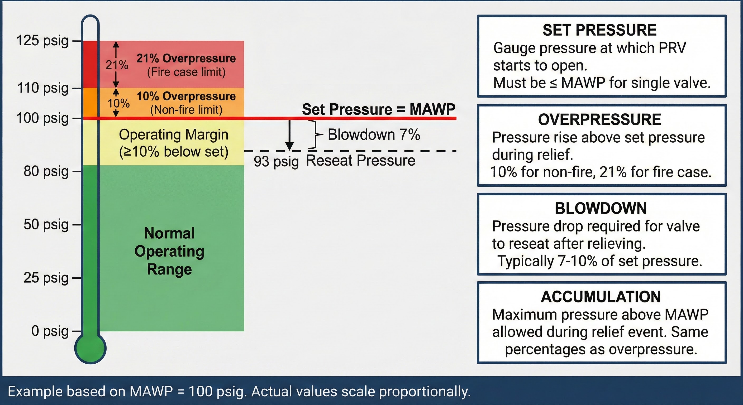
| Set Pressure (Pset) | Gauge pressure at which PRV starts to open (≤ MAWP for single valve) |
| Overpressure | Pressure rise above Pset during relief: 10% normal, 21% fire case |
| Relieving Pressure (P₁) | Sizing basis: P₁ = Pset × (1 + overpressure%) + Patm |
| Blowdown | Pressure drop required for valve to reseat (typically 7–10% of Pset) |
| Backpressure | Pressure at PRV outlet (superimposed + built-up during flow) |
Accumulation Limits (ASME VIII)
| Scenario | Single Valve | Multiple Valves |
|---|---|---|
| Non-fire (operating upset) | 110% MAWP | 116% MAWP |
| Fire exposure | 121% MAWP | 121% MAWP |
PRV Types
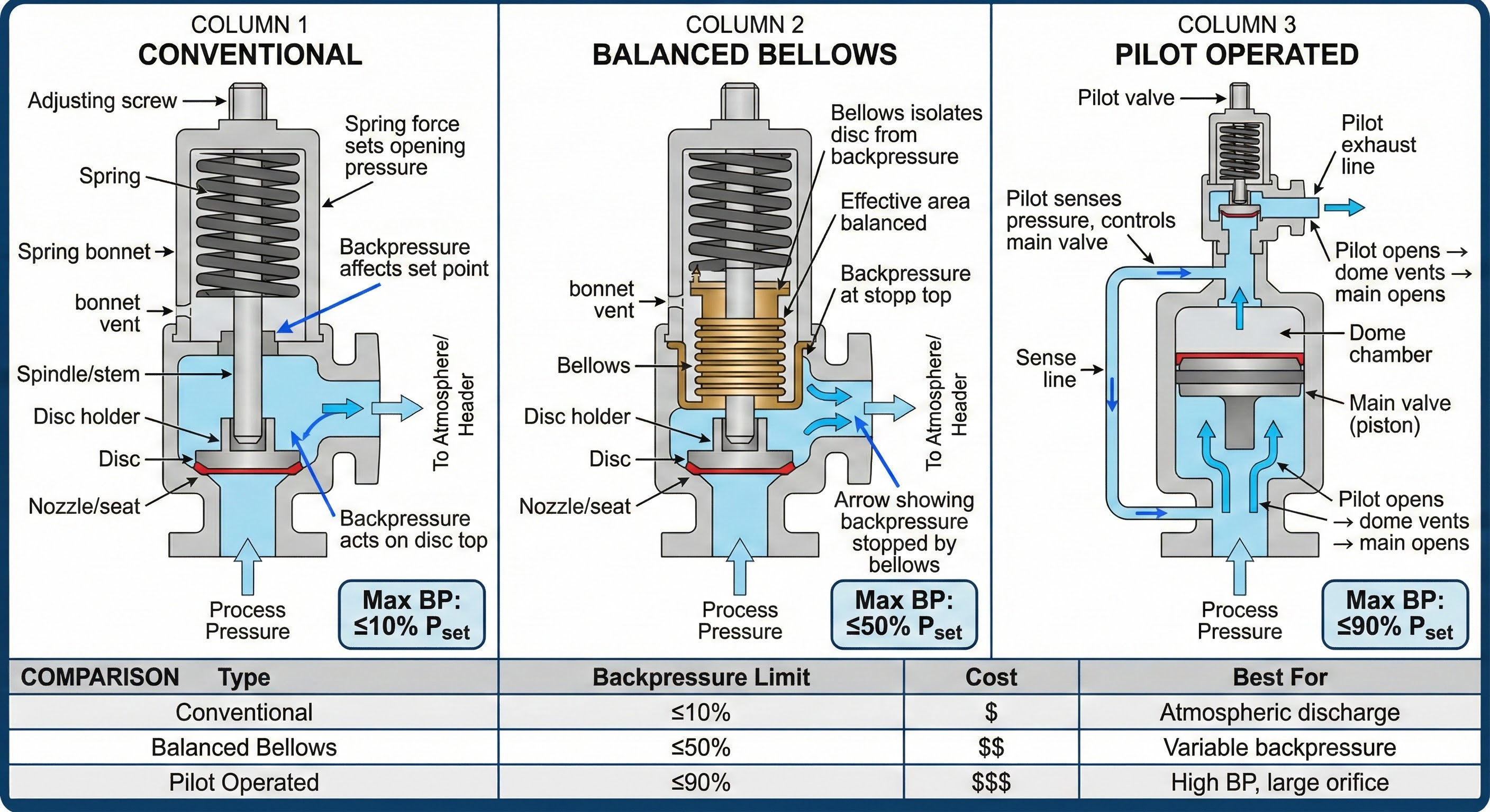
| Type | Max Backpressure | Best For |
|---|---|---|
| Conventional | ≤10% Pset | Atmospheric discharge, low-cost applications |
| Balanced Bellows | ≤50% Pset | Variable backpressure, corrosive service |
| Pilot Operated | ≤90% Pset | High backpressure, large orifices, tight shutoff |
2. Sizing Equations
Gas/Vapor Service (API 520 Eq. 3a)
For critical (choked) flow—typical when backpressure ratio P₂/P₁ is below the critical ratio:
C Factor (Function of k = Cp/Cv)
| k | C | Typical Gas |
|---|---|---|
| 1.15 | 340 | Heavy hydrocarbons |
| 1.26–1.30 | 356–361 | Natural gas, methane |
| 1.40 | 373 | Air, N₂, diatomic gases |
| 1.66 | 398 | Monatomic (He, Ar) |
Critical Pressure Ratio
Flow is critical (choked) when:
Liquid Service (API 520 Eq. 3.1)
⚠ Liquid Kd differs from vapor: Use Kd = 0.65 for liquid, not 0.975. Using the wrong coefficient undersizes the valve by ~50%.
Two-Phase Flow
Two-phase sizing is complex. API 520 Annex C provides the omega method, but for critical applications use vendor software or the conservative approach: size for all-vapor OR all-liquid, whichever requires the larger orifice.
Sizing Example: Gas PRV
Given: 50,000 lb/hr natural gas, Pset = 300 psig, 10% overpressure, T = 150°F, M = 18, k = 1.26, Z = 0.90
P₁ = (300 + 14.7) × 1.10 = 346 psia
C = 356, Kd = 0.975, Kb = 1.0, Kc = 1.0
A = (50,000 / (356 × 0.975 × 346)) × √(610 × 0.90 / 18)
A = 0.416 × 5.52 = 2.30 in²
→ Select Orifice L (2.853 in²)
3. Correction Factors
Discharge Coefficient (Kd)
| Service | Kd |
|---|---|
| Gas/Vapor (critical flow) | 0.975 |
| Liquid | 0.65 |
| Two-phase (typical) | 0.85 |
| With rupture disk (uncertified combo) | Reduce by 10% |
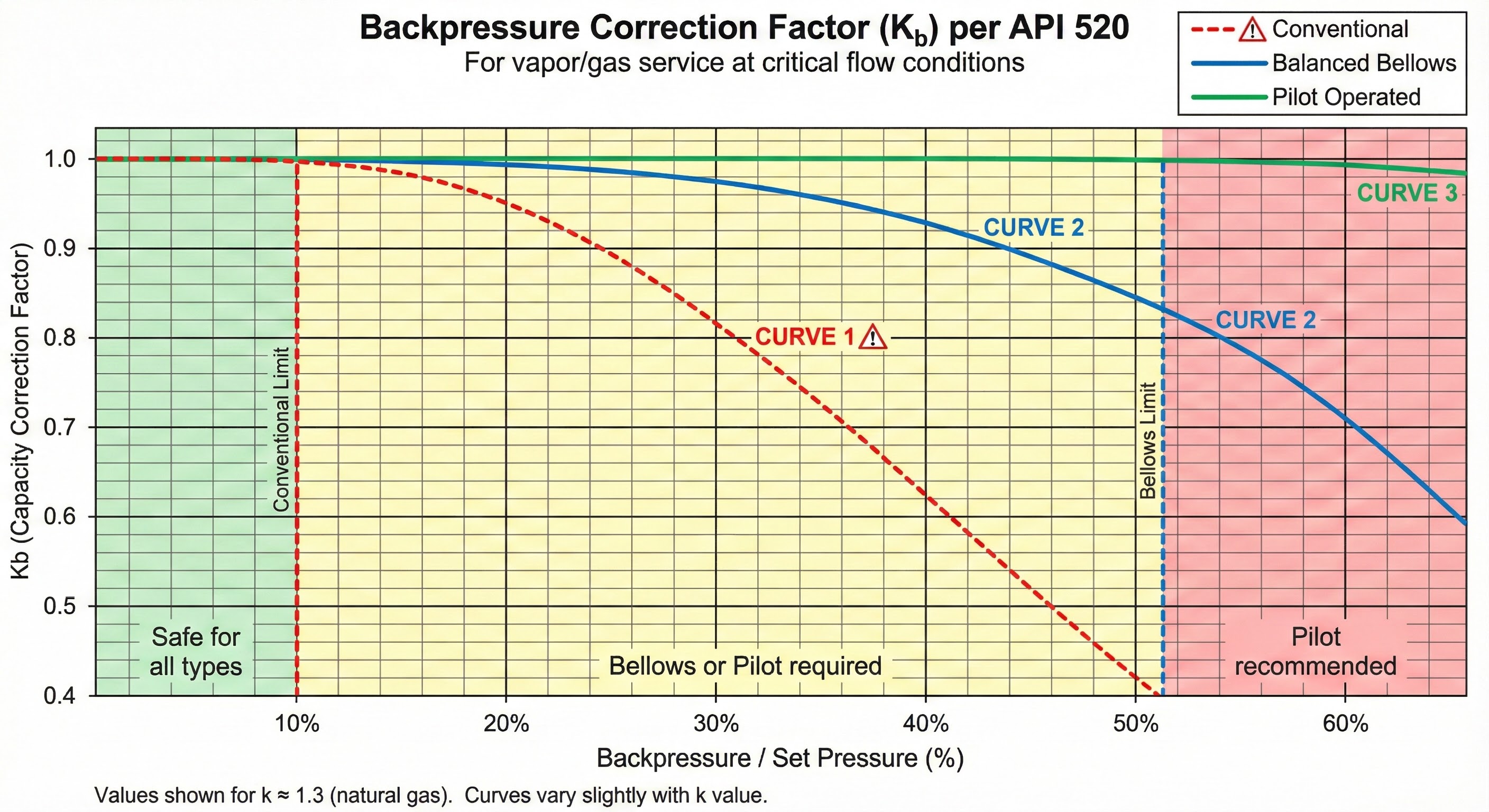
Backpressure Correction (Kb / Kw)
| Valve Type | Backpressure Limit | Kb Notes |
|---|---|---|
| Conventional | ≤10% Pset | Kb = 1.0 up to 10%; drops rapidly above |
| Balanced Bellows | ≤50% Pset | Kb = 0.90–1.0 per manufacturer curve |
| Pilot Operated | ≤90% Pset | Kb ≈ 1.0 across range |
Combination Factor (Kc)
| Configuration | Kc |
|---|---|
| PRV only (no rupture disk) | 1.0 |
| Rupture disk upstream (uncertified) | 0.9 |
| Certified combination (tested) | Use tested value |
Viscosity Correction (Kv) – Liquid Only
For viscous liquids (Re < 10,000), Kv reduces capacity. Calculate Reynolds number:
API 526 Standard Orifices
| Orifice | Area (in²) | Inlet × Outlet |
|---|---|---|
| D | 0.110 | 1" × 2" |
| E | 0.196 | 1" × 2" |
| F | 0.307 | 1½" × 2½" |
| G | 0.503 | 1½" × 3" |
| H | 0.785 | 2" × 3" |
| J | 1.287 | 3" × 4" |
| K | 1.838 | 3" × 4" |
| L | 2.853 | 4" × 6" |
| M | 3.60 | 4" × 6" |
| N | 4.34 | 4" × 6" |
| P | 6.38 | 6" × 8" |
| Q | 11.05 | 6" × 8" |
| R | 16.0 | 8" × 10" |
| T | 26.0 | 8" × 10" |
4. Relief Scenarios
API 521 identifies overpressure scenarios. Evaluate all applicable cases; the governing case (largest required orifice) determines final PRV size.
Common Scenarios
| Scenario | Cause | Sizing Basis |
|---|---|---|
| Blocked Outlet | Downstream valve closed | Max inlet flow (pump curve, control valve Cv) |
| Fire Exposure | External fire heats vessel | Vapor from heat input (API 521 Eq. 5) |
| Tube Rupture | Exchanger tube fails | High-P side flow into low-P side |
| Control Valve Failure | CV fails open | Max flow at upstream pressure |
| Thermal Expansion | Blocked-in liquid heated | Volume expansion rate (small PRV) |
Fire Case Sizing (API 521)
Environment Factor (F)
| Condition | F |
|---|---|
| Bare vessel (no protection) | 1.0 |
| Approved water spray | 0.5 |
| Insulation (1") | 0.3 |
| Insulation (2") | 0.15 |
| Insulation (3") | 0.075 |
| Insulation (4") | 0.05 |
| Fireproofing (concrete) | 0.03 |
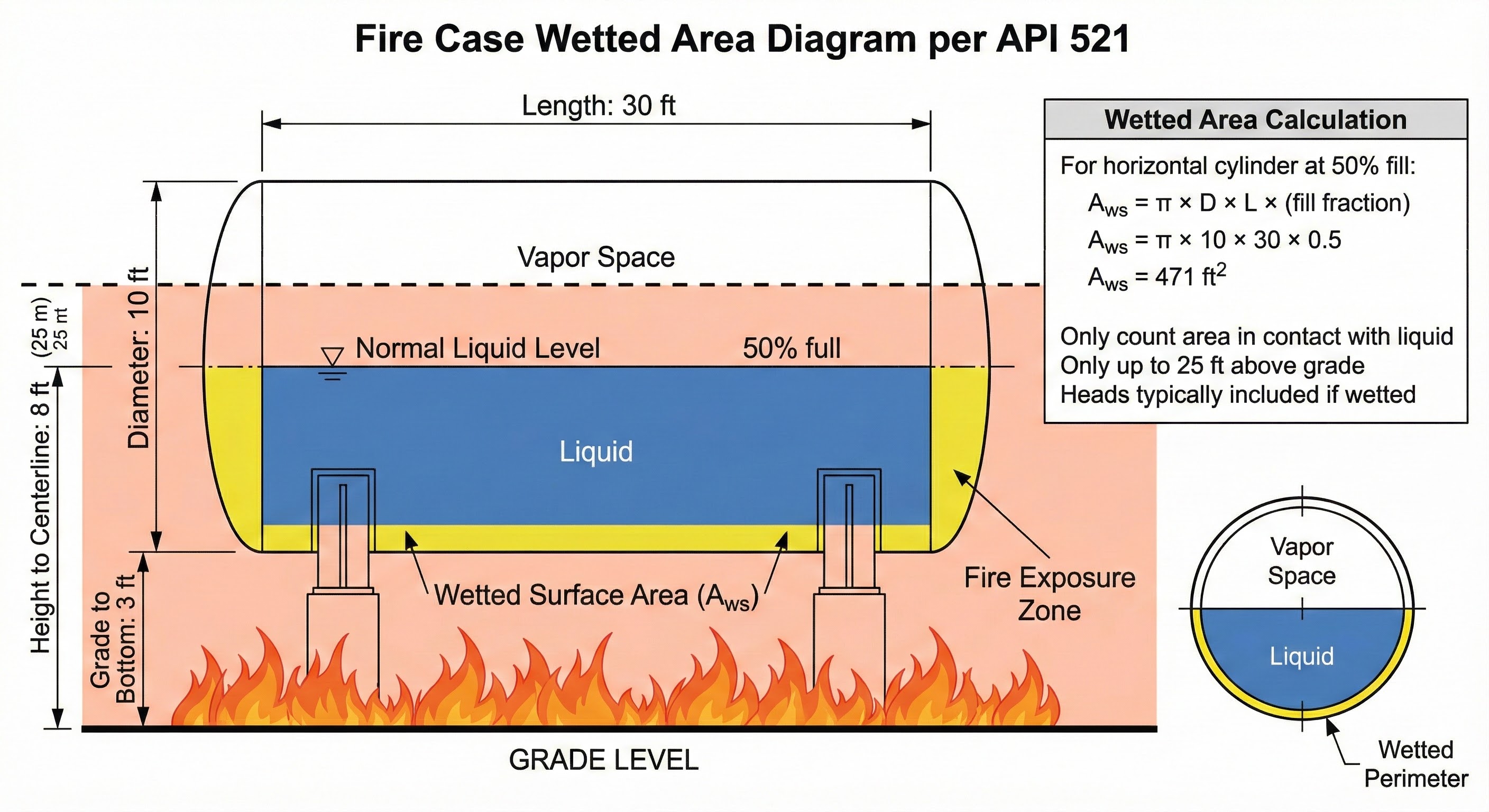
Fire Case Example
Given: Horizontal propane vessel 10 ft × 30 ft, 50% full, bare (F=1.0), MAWP = 250 psig
Wetted area: A = π × 10 × 30 × 0.5 = 471 ft²
Heat input: Q = 21,000 × 1.0 × 4710.82 = 2.67 MMBTU/hr
Propane λ ≈ 130 BTU/lb at relief conditions
Relief rate: W = 2,670,000 / 130 = 20,540 lb/hr
P₁ = (250 + 14.7) × 1.21 = 320 psia (21% fire overpressure)
→ Size using gas equation with propane properties
⚠ Confined fires: If vessel is confined by walls or embankments ≥ vessel height, use exponent 1.0 instead of 0.82 per recent API 521 guidance.
5. Installation
Inlet Piping (API 520 Part II)
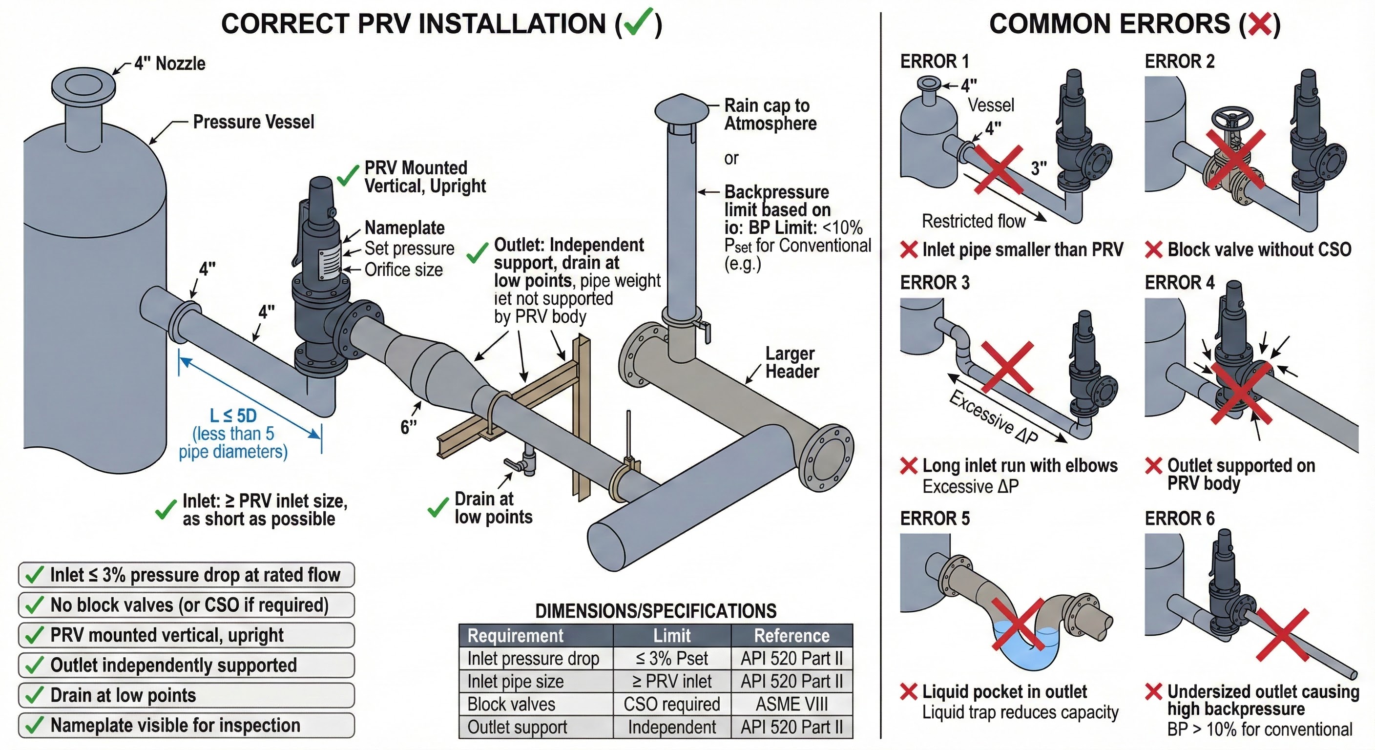
| Requirement | Limit |
|---|---|
| Inlet pressure drop | ≤3% of set pressure at rated flow |
| Inlet pipe size | ≥ PRV inlet size, as short as possible |
| Block valves | Prohibited unless car-sealed-open (CSO) |
| Elbows | Avoid close to inlet; 3–5 diameters straight run if possible |
Outlet Piping
| Valve Type | Max Backpressure |
|---|---|
| Conventional | 10% Pset |
| Balanced Bellows | 30–50% Pset |
| Pilot Operated | Up to 90% Pset |
Outlet Design Rules
- Support independently – never hang outlet pipe from PRV body
- Drain low points – prevent liquid accumulation
- Slope to drain – no liquid pockets in vapor service
- Anchor for reaction force – F = ṁ × V at discharge
Common Errors to Avoid
- ✗ Inlet piping smaller than PRV inlet
- ✗ Inlet ΔP exceeds 3% of set pressure
- ✗ Block valve without CSO and supervision
- ✗ Conventional valve with >10% backpressure
- ✗ Outlet pipe supported on PRV body
- ✗ Liquid traps in outlet piping
- ✗ Sizing for only one scenario (fire may govern)
- ✗ Interpolating between orifice sizes
Testing (API 527)
- Set pressure test: Verify opening at Pset ±3% (or ±3 psi, whichever greater)
- Seat tightness: No visible leakage at 90% Pset per API 527
- Blowdown test: Verify reseat at 90–93% of set pressure
- Periodic recertification: Every 2–5 years per plant procedures
Key Design Considerations
- Critical vs. Subcritical Flow: Most gas PRV sizing assumes critical (choked) flow. Flow is critical when P₂/P₁ ≤ critical ratio (~0.55 for natural gas). Below this ratio, mass flow is independent of downstream pressure.
- Subcritical Flow: When backpressure ratio exceeds the critical ratio, use manufacturer's subcritical flow curves or API 520 Annex B methods.
- Multiple Valves: When a single valve exceeds Size T (26 in²), use multiple smaller valves in parallel. Stagger set pressures by 5% to prevent simultaneous opening.
References
- API 520 Part I – Sizing and Selection (9th Ed., 2014)
- API 520 Part II – Installation (6th Ed., 2015)
- API 521 – Pressure-relieving and Depressuring Systems (6th Ed., 2014)
- API 526 – Flanged Steel PRVs (7th Ed., 2017)
- API 527 – Seat Tightness
- ASME BPVC Section VIII, Div. 1 (UG-125 to UG-136)
Ready to use the calculator?
→ Launch Calculator