Calculate drying time requirements and evaluate air drying, nitrogen drying, and vacuum drying methods to achieve target dewpoint specifications for pipeline commissioning per ASME B31.8.
Pipeline drying removes water introduced during hydrostatic testing, construction, or flooding. Adequate drying prevents corrosion, hydrate formation, and operational problems in gas and liquid pipelines.
Post-hydrotest drying
New construction
Remove water after pressure testing before commissioning gas service.
Maintenance drying
After repairs
Dry pipeline sections opened for maintenance or modification.
Seasonal drying
Intermittent service
Dry pipelines taken out of service to prevent corrosion and freezing.
Product changeover
Multi-product lines
Remove water contamination before product introduction.
Key Concepts
Dewpoint: Temperature at which water vapor condenses from gas (°F or °C)
Relative humidity (RH): Ratio of actual vapor pressure to saturation vapor pressure (%)
Absolute humidity: Mass of water per unit volume of air (grains/ft³ or lb/MMscf)
Drying rate: Rate of moisture removal (lb water/hr)
Saturation: Maximum water vapor capacity at given temperature and pressure
Why drying matters: Water in gas pipelines causes internal corrosion (5-10 mpy rates), hydrate formation (blockages at 32-60°F), freezing damage, and accelerated metallurgical degradation. Proper drying is essential for pipeline integrity and operational reliability.
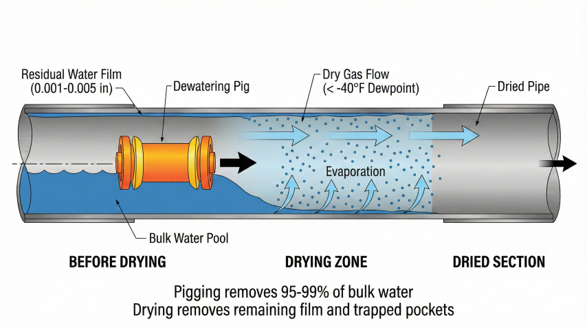
Pipeline drying process: Pigging removes 95-99% of bulk water, drying removes remaining film and trapped pockets.
Key Numbers Example
Example: A 10-mile, 12" pipeline holds ~7,400 bbl of water after hydrostatic testing. Pigging removes 95-99%, leaving ~75-370 bbl as film water and trapped pockets that must be removed by drying.
Consequences of Inadequate Drying
Internal corrosion: Water film promotes electrochemical corrosion, reducing pipe wall thickness
Hydrate formation: Water + gas form solid hydrates blocking flow at low temperatures
Ice formation: Freezing water expands, causing mechanical damage and flow restriction
Microbiologically influenced corrosion (MIC): Bacteria thrive in water, accelerating corrosion
Compressor damage: Liquid water carryover damages downstream compressors
Instrument malfunction: Water in instrumentation lines causes measurement errors
ASME B31.8 Requirements
ASME B31.8 Gas Transmission and Distribution Piping Systems Code requires:
Section 841.32: Pipelines shall be cleaned and dried before being placed in service
Hydrostatic test water removal: Water must be removed within reasonable time after testing
Dewpoint verification: Gas quality must meet specifications before introduction to system
Corrosion prevention: Internal surfaces must be dried to prevent corrosion initiation
Industry Standards
ASME B31.8: Gas pipeline drying requirements
ASME B31.4: Liquid pipeline cleaning and drying
API RP 1171: Pipeline drying practices for commissioning
GPA 2145: Table of Physical Constants for Hydrocarbons (dewpoint data)
ISO 13623: Petroleum and natural gas industries – Pipeline transportation systems
2. Drying Methods
Three primary methods are used for pipeline drying: air drying, nitrogen drying, and vacuum drying. Method selection depends on pipeline volume, required dewpoint, time constraints, and cost.
Method Comparison
Method
Achievable Dewpoint
Typical Duration
Cost Level
Best Application
Air drying
+10°F to -20°F
1-5 days
Low
Moderate dewpoint, long timelines, low-pressure gas
Continuous circulation, precise control, small diameter
[Image: Pipeline Drying System Schematic]
P&ID showing compressor, dryer, pipeline, and dewpoint monitoring arrangement
Air Drying (Dry Air Method)
Compressed dry air blown through pipeline carries away moisture:
Air Drying Process:
1. Source: Compressed air from portable compressors or plant air
2. Conditioning: Pass through refrigerated dryer or desiccant dryer
3. Delivery: Blow through pipeline at 10-30 ft/s velocity
4. Monitoring: Measure outlet dewpoint continuously
5. Endpoint: When outlet dewpoint matches inlet (equilibrium reached)
Advantages:
- Low cost (equipment readily available)
- Simple operation
- No special safety requirements
- Can be done in stages
Disadvantages:
- Limited dewpoint (-20°F typical for refrigerated air)
- Long duration for large pipelines
- Introduces oxygen (pre-commission purge needed)
- Weather-dependent (inlet humidity affects performance)
Typical specifications:
Inlet air dewpoint: -20°F to -40°F
Air velocity: 15-25 ft/s
Flow rate: Size for 15-20 pipe volumes per day
Compressor: 250-500 scfm per 20" pipeline
Nitrogen Drying
High-purity nitrogen gas provides inert, very dry atmosphere:
Nitrogen Drying Process:
1. Source: Liquid nitrogen vaporized or PSA/membrane generators
2. Purity: 99%+ nitrogen, -60°F to -80°F dewpoint
3. Circulation: Continuous or once-through at 5-15 ft/s
4. Monitoring: Outlet dewpoint and oxygen content
5. Endpoint: Outlet dewpoint stable at target (-40°F typical)
Advantages:
- Very low dewpoint achievable (-60°F to -80°F)
- Inert atmosphere (no corrosion, no purge needed)
- Consistent performance (not weather-dependent)
- Can pressurize line during drying (leak test + dry)
Disadvantages:
- High cost (nitrogen supply expensive)
- Requires specialized equipment
- Safety considerations (asphyxiation in confined spaces)
- Venting considerations (GHG, noise)
Nitrogen consumption estimate:
V_N2 (scf) = Pipeline Volume (ft³) × Number of Turnovers × 1.05
Turnovers = 20-50 (depends on initial moisture, target dewpoint)
Example: 20" × 10 miles pipeline
Volume = π/4 × (20/12)² × 10 × 5,280 = 115,193 ft³
Turnovers = 30 (moderate drying)
N2 required = 115,193 × 30 × 1.05 = 3,628,580 scf = 3.63 MMscf
At $5/Mscf: Cost = $18,143 for nitrogen
Vacuum Drying
Reduce pressure to boil off water at low temperature:
Vacuum Drying Principle:
Water boiling point decreases with pressure:
- 1 atm (14.7 psia): 212°F
- 0.5 psia: 79.6°F
- 0.1 psia: 46.7°F
- 0.02 psia: 20.8°F (below freezing at 1 atm!)
Process:
1. Seal pipeline, connect vacuum pump
2. Evacuate to 0.1-1.0 psia
3. Water boils and evaporates at ambient temperature
4. Vacuum pump removes water vapor
5. Hold vacuum until no more water vapor generated
6. Break vacuum with dry nitrogen
7. Verify dewpoint
Advantages:
- Fastest method (hours vs. days)
- Excellent dewpoint (-80°F to -100°F achievable)
- No gas consumption (just vacuum pump power)
- Works at ambient temperature
Disadvantages:
- Very high equipment cost (large vacuum pumps, condensers)
- Limited to smaller diameter/shorter length (ΔP limitations)
- Requires robust pipe fittings (full vacuum stress)
- Safety concerns (pipe collapse if defective)
- Freezing risk (water freezes as pressure drops, blocking evacuation)
Vacuum drying limitations:
Max practical length: 1-5 miles (depends on diameter)
Requires thick-wall pipe (withstand external pressure)
Must verify pipe design for vacuum (1 atm external - 0 internal = 14.7 psi)
Hybrid Methods
Combining methods for optimal performance and cost:
Air + nitrogen: Initial drying with air to -20°F, final polish with nitrogen to -40°F (reduces nitrogen cost)
Nitrogen + vacuum: Nitrogen drying to remove bulk water, vacuum for final drying to ultra-low dewpoint
Pig + air: Push water slug out with pig, then air dry to remove residual moisture
Desiccant Process:
1. Install portable desiccant dryer (molecular sieve or silica gel)
2. Circulate pipeline gas through dryer
3. Desiccant adsorbs water vapor
4. Monitor outlet dewpoint
5. Regenerate desiccant as it saturates (heat + purge)
6. Continue until target dewpoint stable
Advantages:
- Very low dewpoint (-100°F possible)
- Closed-loop (no venting)
- Precise control
- Can operate at elevated pressure
Disadvantages:
- Expensive equipment rental
- Limited to smaller pipelines (flow rate constraints)
- Requires power for circulation and regeneration
- Desiccant replacement/regeneration cost
Typical application:
Pipeline diameter: 4-16 inches
Length: Up to 10 miles
Duration: 1-3 days with automated regeneration
Methanol Slug Treatment
Principle: Methanol absorbs water (0.7 lb H₂O per lb MeOH)
Process:
1. Calculate water to remove from GPSA charts
2. Size methanol slug (typically 20-40% of pipe volume)
3. Push slug through with dry gas or nitrogen
4. Collect methanol/water mixture at downstream end
Best for: Gathering lines, hydrate prevention, smaller-diameter lines
Caution: Toxic/flammable - full PPE required
Dewatering Pigs (Pre-Drying Mechanical Removal)
Run before any drying method to remove 90-99% of bulk water:
Pig Type
Removal
Application
Medium-density foam
70-90%
Initial pass
High-density foam
85-95%
Second pass
Bi-directional + squeegee
95-99%
Final dewatering
Best practice: Run 2-3 pigs in sequence before drying to minimize residual water. Dewatering pigging is the most cost-effective first step regardless of which drying method follows.
3. Dewpoint Specifications
Target dewpoint depends on pipeline service, operating temperature, and hydrate formation conditions. Specifications ensure water content is below critical levels for corrosion and hydrate prevention.
Dewpoint Requirements by Service
Service Type
Typical Dewpoint
Basis/Reason
Dry natural gas transmission
-20°F to -40°F
Prevent hydrates at operating pressure/temperature
Sour gas (H₂S present)
-40°F to -60°F
Prevent corrosion (water + H₂S = acid)
Gathering lines (wet gas)
+15°F to -10°F
Moderate requirements, processed downstream
High-pressure storage
-40°F to -80°F
Stringent to prevent hydrates at high pressure
Instrument gas
-40°F to -80°F
Protect sensitive instruments from moisture
Compressed air systems
-40°F
Standard compressed air quality (ISO 8573)
Liquid pipelines (NGL, crude)
50 ppm water max
Specification (not dewpoint), prevent free water
Hydrate Formation Conditions
Gas hydrates are ice-like crystalline solids that form when water molecules encapsulate gas molecules under specific pressure-temperature conditions. They can block flow completely.
[Image: Hydrate Formation Phase Envelope]
P-T diagram showing hydrate formation region for 0.6 SG natural gas
Hydrate Formation Temperature (Natural Gas, ~0.6 SG):
Towler & Mokhatab (2005) correlation (γ = 0.6 SG):
T_hydrate (°F) = 13.47·ln(P) + 34.27·ln(γ) − 1.675·ln(P)·ln(γ) − 20.35
Where P = absolute pressure (psia), γ = gas gravity (0.6)
Examples (γ = 0.6):
P = 300 psia → T_hydrate ≈ 44°F
P = 500 psia → T_hydrate ≈ 51°F
P = 1,000 psia → T_hydrate ≈ 61°F
P = 1,500 psia → T_hydrate ≈ 67°F
(The older Katz fit ran ~10°F high here — non-conservative for hydrate-margin warnings.)
Interpretation:
At 1,000 psia, hydrates can form if gas temperature drops below ~70°F
AND free water is present. The dewpoint specification must ensure
no liquid water forms at the coldest expected operating temperature.
Safety margin:
Specify dewpoint 20-30°F below minimum expected operating temperature
Dewpoint vs. Water Content
Dewpoint (temperature) and water content (mass) are related through vapor pressure:
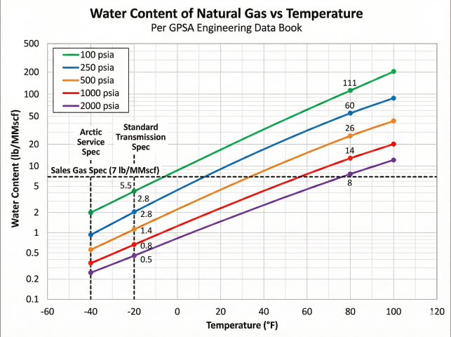
[Image: GPSA Water Content Chart]
Water content (lb/MMscf) vs temperature at various pressures (GPSA Fig. 20-3 style)
Water Content Calculation:
W = (e_s × MW_water × 10⁶) / (P_total × R × T)
Where:
W = Water content (lb/MMscf)
e_s = Saturation vapor pressure of water at dewpoint (psia)
MW_water = 18 lb/lbmol
P_total = Total pressure (psia)
R = 10.73 psia·ft³/lbmol·°R
T = Temperature (°R)
Antoine Equation for Saturation Vapor Pressure:
log₁₀(e_s) = A - B/(C + T)
Where T is in °C, e_s in mmHg (convert to psia)
Constants: A = 8.07131, B = 1730.63, C = 233.426
Simplified conversion table (illustrative, LOW pressure):
Dewpoint (°F) | Water Content, low-pressure illustration (lb/MMscf)
+32 | 48
0 | 28
-20 | 14
-40 | 6
-60 | 2.5
-80 | 1.0
NOTE: these are NOT 1,000-psia values — water content falls sharply
with pressure (~15-20x lower at 1,000 psia). For pressure-specific
figures use the GPSA water-content table below (e.g. -20°F -> 0.8 lb/MMscf @1,000 psia).
Measuring Dewpoint
Instrument Type
Range
Accuracy
Application
Chilled mirror hygrometer
-100°F to +100°F
±1°F
Laboratory reference, spot checks
Capacitive sensor
-40°F to +140°F
±2-3°F
Continuous monitoring, portable meters
Aluminum oxide sensor
-110°F to +68°F
±3-5°F
Very low dewpoints, natural gas quality
Psychrometer (wet/dry bulb)
+20°F to +120°F
±3-5°F
High humidity, inexpensive, manual
Dew cup (manual)
0°F to +100°F
±5°F
Field verification, visual
Industry Standard Dewpoints (Quick Reference)
Service
Dewpoint Spec
Gathering (<500 psia)
-20°F @ operating P
Transmission (500-1000 psia)
-20°F to -40°F @ 1000 psia
High-pressure (>1000 psia)
-40°F @ operating P
Arctic service
-60°F to -80°F
Sales gas (contract)
7 lb/MMscf @ 14.7 psia
Pressure Effect on Dewpoint
Important: Dewpoint rises with pressure compression.
Gas at -20°F dewpoint @ 500 psia
→ Compressed to 1,000 psia
→ New dewpoint ≈ -10°F (rises ~10°F per 2x pressure)
Best practice: Specify dewpoint at MAOP
"Dewpoint ≤ -20°F at 1,200 psig"
Dewpoint vs. water content: Dewpoint is intuitive for operations (relates directly to hydrate risk). Water content (lb/MMscf) is used in contracts. Always specify pressure basis.
Acceptance Criteria
Define pass/fail criteria for drying completion:
Typical Acceptance Criteria:
1. Dewpoint stability:
Outlet dewpoint ≤ target dewpoint for 2 hours continuous
2. Dewpoint differential:
(Inlet dewpoint - Outlet dewpoint) < 5°F (near equilibrium)
3. Multiple measurements:
Three consecutive dewpoint readings within spec, 1 hour apart
4. Cold temperature verification:
For -40°F spec, cool sample to 0°F and verify no condensation
5. Volume throughput:
Minimum 20-50 pipeline volumes of dry gas passed through
Example specification:
"Pipeline drying complete when outlet dewpoint measured at -42°F
or lower for 4 consecutive hours, with inlet-outlet differential
less than 3°F, after minimum 30 pipeline volumes throughput."
Specification principle: Target dewpoint must be below the LOWEST expected pipeline temperature with adequate safety margin (20-30°F) to prevent any condensation during operation, including upset/shutdown conditions.
4. Drying Time Calculations
Drying time depends on pipeline volume, initial water content, target dewpoint, drying gas flow rate, and method efficiency. Accurate estimates are essential for project scheduling.
Water Volume Calculation
Free Water Volume (After Hydrotest):
V_water = Pipeline Volume × Water Remaining Factor
Water Remaining Factor:
- After air blowdown: 2-5% (water film on walls)
- After pigging: 0.5-2% (residual water)
- After methanol flush: 0.1-0.5% (trace water)
Example:
20" diameter, 10 miles long
Volume = π/4 × (20/12)² × 10 × 5,280 = 115,193 ft³
Water after pigging: 115,193 × 0.02 = 2,304 ft³ = 17,233 gallons
Water mass:
17,233 gal × 8.34 lb/gal = 143,731 lb water to remove
Residual Water Estimation (Film Method)
After pigging (95-99% removed):
Film method: M = π × D × L × t × ρ
Where t = 0.001-0.005" film thickness
Example - 10 mi × 12" pipe:
M = π × 1.0 ft × 52,800 ft × 0.000167 ft × 62.4 lb/ft³
M = 1,730 lb ≈ 200 gallons residual water (after pigging)
Water Content of Natural Gas (GPSA)
Water content of natural gas vs temperature at various pressures. Source: GPSA.
Temp (°F)
100 psia
500 psia
1000 psia
-40
2.0
0.6
0.35
-20
5.5
1.4
0.8
40
34
7.8
4.3
80
111
26
14
Water content in lb/MMscf. Source: GPSA.
Methanol Slug Requirements
MMeOH = (Wvapor + Wresidual) / (0.7 × P)
Where:
Wvapor = Vapor-phase water = (Winitial - Wtarget) × V
Wresidual = Residual free water after pigging (typically 1-2% of pipe volume)
0.7 = Methanol absorption capacity (lb H₂O/lb MeOH)
P = Methanol purity (fraction, e.g. 1.0 for 100%)
Example:
10 mi × 12" at 500 psia, 80°F → -20°F dewpoint
W_initial = 26 lb/MMscf, W_target = 1.4 lb/MMscf
V = 0.041 MMscf
Vapor water = (26 - 1.4) × 0.041 = 1.0 lb
Residual water (1.5% of 310,000 gal × 8.34 lb/gal) ≈ 38,800 lb
Total water = 1.0 + 38,800 ≈ 38,800 lb
Methanol = 38,800 / 0.7 = 55,400 lb = 8,360 gal
Note: Residual free water dominates methanol requirements.
Vapor-phase water is negligible in comparison for post-hydrotest drying.
Drying Air Required
Moisture Carrying Capacity:
Water-carrying capacity of the dry air leaving the pipe saturated at ~70°F:
C_air ≈ 1,180 lb water / MMscf
Cold, dry inlet air picks up moisture as it passes through the line and
leaves saturated at the pipe temperature. At 70°F, saturated air carries
~1,180 lb water per MMscf (humidity ratio ~0.0158 lb/lb × ~76,000 lb air/MMscf)
— this is the AIR's moisture capacity, far larger than gas-phase water-content
figures.
Total air volume required:
V_air = W_water / C_air
Where W_water = total water to remove
Example Calculation:
Dry air, saturating to ~1,180 lb/MMscf at 70°F outlet
Water to remove: 143,731 lb
V_air = 143,731 / 1,180 = 122 MMscf = 0.122 Bcf
Drying time:
If air flow = 1,000 scfm:
Time = 122 MMscf / (1,000 scfm × 60 min/hr × 24 hr/day)
Time = 122,000 Mscf / 1,440 Mcf/day = 85 days
[Air drying is still slow at low flow - use higher flow rates and/or
remove bulk water by pigging first]
Realistic scenario (with pigging):
Pig removes 95% of water → Only 7,187 lb to remove by air
V_air = 7,187 / 1,180 = 6.1 MMscf
At 5,000 scfm air flow:
Time = 6.1 MMscf / (5,000 × 60 × 24) = 0.85 days (~20 hours)
Nitrogen Drying Time
Similar calculation but with much drier inlet gas:
Nitrogen Drying Example:
Dry N2 saturating at 70°F carries ~1,180 lb water/MMscf at full
saturation. Nitrogen is expensive, so it is run at partial saturation:
- Target 80% saturation → C_eff = 1,180 × 0.8 = 944 lb/MMscf
- Water to remove: 7,187 lb (after pigging)
- V_N2 = 7,187 / 944 = 7.6 MMscf
At 2,000 scfm nitrogen flow:
Time = 7.6 MMscf / (2,000 × 60 × 24) = 2.6 days
Acceleration through turnovers:
Multiple turnovers (20-30) with drier nitrogen reduces effective time:
Time_effective = 21.1 / (efficiency factor of 3-5) = 4-7 days
Vacuum Drying Time
Vacuum Drying Duration:
Much faster because water boils off at ambient temperature.
t_dry = (W_water × λ) / (Pump Rate × η)
Where:
W_water = Water mass (lb)
λ = Latent heat of vaporization (1,000 Btu/lb at reduced pressure)
Pump Rate = Vacuum pump capacity (cfm, corrected for vapor)
η = Efficiency (0.5-0.7 for practical systems)
Example:
7,187 lb water to evaporate
Pump: 1,000 cfm @ 0.1 psia
Energy required: 7,187 × 1,000 = 7,187,000 Btu
Pump rate in terms of water removal:
~500 lb/hr (depends on temperature, pump size, condensing capacity)
Time = 7,187 / 500 = 14.4 hours
Practical duration:
With setup, multiple evacuations, verification: 1-2 days total
Factors Affecting Drying Time
Factor
Effect on Drying Time
Optimization Strategy
Ambient temperature
Higher temp = faster (more evaporation)
Schedule drying in warm months if possible
Inlet gas dewpoint
Lower dewpoint = faster (more capacity)
Use driest available gas (refrigerated/desiccant dryer)
Flow rate/velocity
Higher flow = faster (mass transfer)
Maximize flow within erosion limits (30 ft/s max)
Initial water content
More water = longer time
Remove bulk water by pigging before air/N2 drying
Pipeline material
Rust/scale holds water = longer
Clean/coat pipe interior before hydrotest
Elevation changes
Low points trap water = much longer
Install drain points, pig multiple times, tilt line if possible
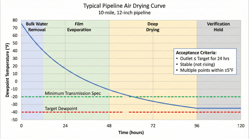
[Image: Typical Drying Curve]
Outlet dewpoint vs time showing exponential decay to target specification
Rule-of-Thumb Estimates
Quick estimates for project planning:
Air Drying (after pigging):
Duration (days) = Pipeline Length (miles) / 2
Example: 20 mile line → 10 days air drying
Range: 5-15 days depending on diameter, water removal efficiency
Nitrogen Drying:
Duration (days) = Pipeline Length (miles) / 3
Example: 20 mile line → 7 days nitrogen drying
Range: 3-10 days depending on target dewpoint
Vacuum Drying:
Duration (hours) = Pipeline Volume (Mft³) × 5
Example: 138 Mft³ → 690 hours ≈ 29 days
Practical limit: 2-3 days for setup + drying + verification
Add contingency:
Multiply estimated time by 1.5-2.0 for schedule planning
(Weather delays, equipment failures, re-testing)
5. Operational Procedures
Pre-Drying Steps
Water removal: After hydrotest, drain water from low points and blow down line with compressed air
Pigging: Run 2-3 foam pigs to push out bulk water (reduces water by 95-98%)
Inspection: Verify water removal through drain valves, no standing water in line
Equipment setup: Install air dryer, compressors, nitrogen supply, and dewpoint monitoring
Baseline measurement: Measure initial outlet dewpoint (will be very high, near saturation)
Air Drying Procedure
Step-by-Step Air Drying:
1. Setup:
- Connect air compressor to inlet
- Install refrigerated or desiccant dryer on compressor discharge
- Connect dewpoint meter to outlet (with sample cooler)
- Open all vents and drains during initial blowdown
2. Initial Blowdown (Day 1):
- Flow air at maximum safe velocity (20-30 ft/s)
- Monitor outlet - will be very wet initially
- Continue until outlet humidity drops significantly (12-24 hours)
3. Steady-State Drying (Days 2-N):
- Maintain continuous air flow
- Monitor inlet and outlet dewpoint every 2-4 hours
- Plot dewpoint vs time (should decrease exponentially)
- Adjust flow rate if outlet dewpoint plateaus
4. Verification Phase:
- When outlet dewpoint approaches target, increase monitoring frequency
- Require 2-4 hours of stable readings at or below target
- Verify inlet-outlet differential < 5°F (equilibrium)
5. Final Acceptance:
- Collect outlet sample in chilled dew cup (0°F)
- Verify no condensation = dewpoint < 0°F
- Document flow volumes, time, dewpoint readings
- Seal pipeline with dry nitrogen or process gas
Safety considerations:
- Vent air discharge away from personnel (high velocity)
- Monitor oxygen levels if working in confined spaces
- Verify pressure rating of line (don't exceed MAOP during drying)
Nitrogen Drying Procedure
Nitrogen Drying Steps:
1. Initial Purge:
- Displace air with nitrogen (3-5 line volumes)
- Verify oxygen < 1% at outlet (use oxygen analyzer)
2. Continuous Flow Drying:
- Establish nitrogen flow at 5-15 ft/s
- Monitor outlet dewpoint continuously
- Calculate turnover rate (flow / line volume)
- Target 20-50 turnovers for -40°F to -60°F dewpoint
3. Optimization:
- If dewpoint stagnates, increase flow rate (better mass transfer)
- If nitrogen cost is concern, pause periodically for settling, then resume
- Monitor nitrogen consumption vs budget
4. Acceptance:
- Outlet dewpoint stable at target for 4 hours
- Differential < 3°F
- Seal line under positive nitrogen pressure (50-100 psig)
- Leave nitrogen blanket until commissioning
Nitrogen supply options:
- Liquid nitrogen tankers with vaporizers (most common)
- Membrane nitrogen generators (for longer campaigns)
- PSA nitrogen generators (if electricity available)
Vacuum Drying Procedure
Vacuum Drying Process:
1. Pre-Check:
- Verify pipe design for external pressure (14.7 psi)
- Inspect all flanges, closures for vacuum-tight seal
- Install vacuum pumps, condensers, instrumentation
2. Initial Evacuation:
- Start vacuum pumps, reduce pressure to 1-5 psia
- Water begins evaporating (may see temperature drop)
- Monitor pressure - should continue dropping
3. Deep Vacuum:
- Reduce to 0.1-0.5 psia
- Hold at this pressure for 4-24 hours
- Water evaporation rate slows as remaining water decreases
4. Verification:
- Isolate pipeline (close vacuum valves)
- Monitor pressure rise over 1 hour
- If pressure stable (no rise) → drying complete
- If pressure rises > 0.1 psi → continue evacuating (water still present)
5. Nitrogen Break:
- Open nitrogen valve slowly (don't shock pipe)
- Pressurize to 50-100 psig with dry nitrogen
- Measure dewpoint (should be -60°F or lower)
Safety critical:
- External pressure can collapse thin-wall pipe
- All personnel clear during evacuation
- Emergency venting procedure if pipe shows distress
Common Problems and Solutions
Problem
Symptoms
Likely Cause
Solution
Dewpoint plateau
Outlet dewpoint stops improving
Water trapped in low points, equilibrium reached
Increase flow rate, run additional pig, tilt pipeline
High outlet dewpoint
Never reaches target
Inlet air too wet, leak in line, large water volume
Improve inlet air quality, leak test line, more pigging
Erratic readings
Dewpoint fluctuates wildly
Liquid water slugs, instrument location
Install sample cooler, relocate probe downstream
Slow progress
Taking much longer than estimated
Underestimated water volume, low flow rate
Add compressors, switch to nitrogen, extended duration
Acceptance test results: Final dewpoint readings, witness signatures, photos/video
Deviation reports: Any excursions, delays, or non-conformances during drying
As-built conditions: Pipeline condition (rust, scale, cleanliness) before drying
Gas chromatograph analysis: If required, verify oxygen, CO2, H2S removed (N2 purge)
Post-Drying Protection
Preserve drying results until commissioning:
Nitrogen Blanket:
After drying complete:
1. Pressurize line to 50-200 psig with dry nitrogen
2. Monitor pressure weekly - pressure drop indicates leak
3. Top up nitrogen as needed to maintain positive pressure
4. Before commissioning, verify dewpoint still acceptable (sample)
Duration:
Can maintain nitrogen blanket for months if needed
Cost: ~$100-500/month for typical pipeline (nitrogen makeup)
Alternative:
For long delays (>6 months), consider mothballing:
- Fill with nitrogen to 75% MAOP
- Install corrosion inhibitor
- Periodic inspection/pressure checks
Best practice summary: Remove bulk water by pigging (95%+), use appropriate drying method for target dewpoint, continuously monitor outlet dewpoint, verify acceptance with multiple measurements, maintain nitrogen blanket until commissioning. Plan for 2× estimated duration to account for contingencies.
Five primary methods: air drying (lowest cost, 5-20 days), nitrogen drying (very low dewpoint, 2-7 days), vacuum drying (fastest, 1-3 days, smaller pipes), methanol slug treatment (gathering lines, hydrate prevention), and desiccant/molecular-sieve drying (precise control). Most projects pre-pig to remove 95-99% of bulk water before any drying method.
What dewpoint is required for natural gas pipelines?+
Typical specifications: -20°F for gathering lines (<500 psia), -20°F to -40°F for transmission (500-1000 psia), -40°F for high-pressure service, and -60°F to -80°F for arctic and sour gas service. Dewpoint should be specified 20-30°F below the lowest expected operating temperature, and at the operating pressure (since dewpoint rises with compression).
What standards govern pipeline drying?+
ASME B31.8 Section 841.32 (gas transmission/distribution), ASME B31.4 (liquid pipelines), API RP 1171 (commissioning practices), and GPA 2145 (water content data). Per ASME B31.8, pipelines must be cleaned and dried before being placed in service, with dewpoint verification before introducing product gas.
How is drying time calculated?+
Drying time depends on water mass to remove, drying gas moisture-carrying capacity (Δw), and gas flow rate: Time = water mass / (Δw × flow). Pre-pigging (removes 95% of water) reduces drying time dramatically. Rule of thumb: air drying ≈ length(mi)/2 days, nitrogen drying ≈ length(mi)/3 days, vacuum drying 1-3 days regardless of length. Add 50-100% contingency.
What is dewatering pigging?+
Mechanical removal of bulk water from a pipeline by running pigs (medium-density foam, high-density foam, or bi-directional squeegee). Pigging removes 90-99% of liquid water before the drying step. A typical sequence runs 2-3 pigs (foam then squeegee) to minimize residual water that the drying method must evaporate.
How is dewpoint measured in the field?+
Common instruments: chilled mirror hygrometer (lab reference, ±1°F), capacitive sensor (portable field, ±2-3°F), aluminum oxide sensor (online monitoring at very low dewpoints, ±3-5°F). Sample at three points: inlet (verify dry supply), outlet (primary, slowest to dry), and low points (water accumulates). Acceptance requires outlet dewpoint ≤ target for 24 hours continuous.