1. Buoyancy Principles
Pipelines submerged in water experience an upward buoyancy force equal to the weight of water displaced. For stability, the pipeline must have sufficient negative buoyancy (downward weight exceeding buoyancy).
Archimedes' Principle
Water Densities
| Water Type | Density (lb/ft³) | Density (lb/gal) |
|---|---|---|
| Fresh water | 62.4 | 8.34 |
| Brackish water | 63.0-63.8 | 8.42-8.53 |
| Seawater (typical) | 64.0 | 8.56 |
| Seawater (high salinity) | 64.3-65.0 | 8.60-8.69 |
| Saturated brine | 75.0 | 10.0 |
Pipeline Weight Components
Steel
Primary weight
Base structural mass; check wall thickness and grade.
Corrosion coat
Diameter impact
Adds OD for buoyancy; little added weight.
Weight coat
Concrete
Main tool for negative buoyancy; pick density carefully.
Contents
Fluid weight
Gas is negligible; liquids can add stability.
2. Force Calculations
Net buoyancy is the difference between downward weight and upward buoyancy force.
Weight Calculations
Coating Weights
| Coating Type | Typical Thickness | Density (lb/ft³) |
|---|---|---|
| FBE (Fusion Bonded Epoxy) | 14-25 mils | 87 |
| 3-Layer PE/PP | 80-120 mils | 56-58 |
| Coal tar enamel | 90-125 mils | 75-80 |
| Concrete (standard) | 1.5-4.0 inches | 140-165 |
| Concrete (high density) | 1.5-4.0 inches | 165-190 |
| Concrete (iron ore) | 1.5-4.0 inches | 190-250 |
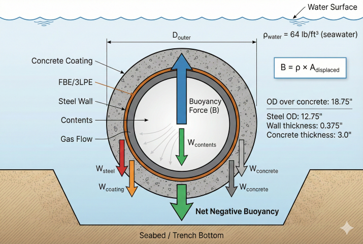
Concrete Weight Coating
Buoyancy Force
Example: Buoyancy Calculation
Given: 12.75" OD × 0.375" WT pipe, 3" concrete coating (165 lb/ft³), seawater
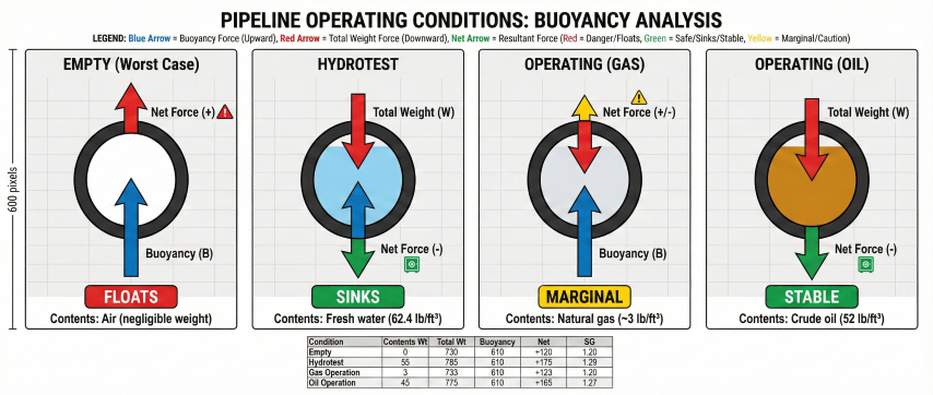
3. Stability Requirements
Submerged pipelines must maintain adequate negative buoyancy under all operating and environmental conditions.
Negative Buoyancy Factor
Set SG target. Pick safety factor based on environment (river, marsh, offshore).
Check conditions. Evaluate empty, hydrotest, and operating contents; use the worst uplift case.
Add weight. Size concrete or anchors to meet SG target with margin.
Design Conditions
| Condition | Contents | Water | Notes |
|---|---|---|---|
| Installation (flooded) | Seawater | Seawater | Heaviest contents condition |
| Hydrotest | Fresh water | Site specific | May add weight |
| Operation (gas) | Gas (~2-5 lb/ft³) | Site specific | Lightest - worst case |
| Operation (oil) | Oil (50-55 lb/ft³) | Site specific | Adds stability |
| Depressured/empty | None (air) | Site specific | Often worst case |
Hydrodynamic Forces
In addition to static buoyancy, pipelines may experience:
- Wave loading: Oscillating lift and drag forces
- Current drag: Steady horizontal force
- Vortex-induced vibration: Cyclic lift from vortex shedding
- Upheaval buckling: Thermal expansion in buried lines
⚠ Flooded condition: Always check buoyancy assuming the trench floods with the highest-density water expected. Saturated soil can exert significant uplift on buried pipes.
4. Weight Coating Design
When pipe steel weight alone is insufficient, concrete weight coating or other methods provide the required negative buoyancy.
Concrete Thickness Calculation
Density pick
140–190 lb/ft³
Standard to high-density concrete covers most cases.
Iteration
Diameter changes
t_conc increases OD → raises buoyancy; iterate to converge.
Construction
Field checks
Verify actual coating thickness and density in QC.
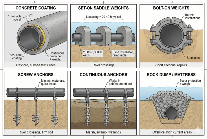
Alternative Weighting Methods
| Method | Application | Advantages |
|---|---|---|
| Concrete coating | Continuous subsea lines | Protection + weight |
| Set-on weights (saddle) | River crossings | Field installable |
| Bolt-on weights | Retrofits, short sections | Removable |
| Continuous anchors | Marsh, swamp | Works in soft soil |
| Screw anchors | River crossings | Minimal materials |
| Rock/mattress cover | Offshore stabilization | Scour protection |
Saddle Weight Spacing
Concrete Coating Standards
- DNV-OS-F101: Submarine pipeline systems
- API RP 17A: Subsea production system design
- ASME B31.4/B31.8: Onshore pipeline references
- ISO 21809-5: Concrete weight coating
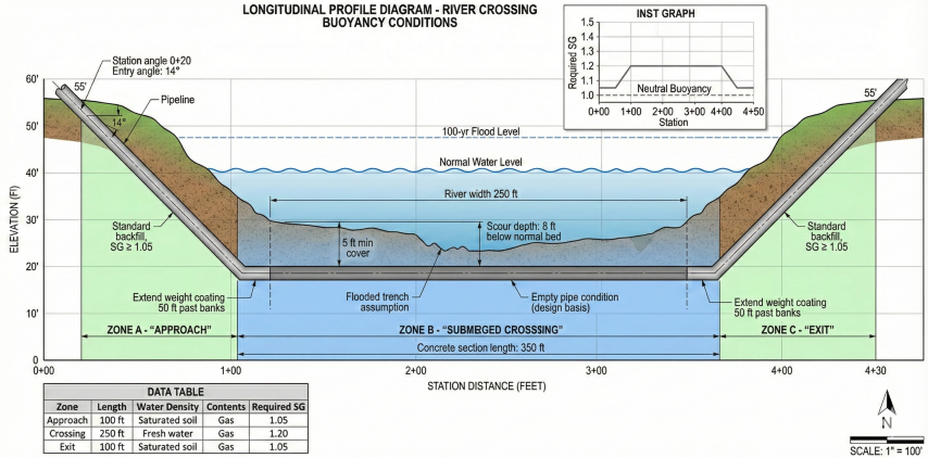
5. Applications
Buoyancy calculations are essential for various submerged pipeline scenarios.
Common Applications
| Application | Typical SG Requirement | Key Considerations |
|---|---|---|
| River/creek crossing | 1.10-1.25 | Scour, flood levels |
| Wetland/marsh | 1.20-1.40 | Soft soil, water table |
| HDD exit in water | 1.10-1.20 | Pullback forces |
| Offshore pipeline | 1.10-1.50 | Waves, currents, installation |
| Lake crossing | 1.05-1.15 | Generally calm conditions |
| Flood plain | 1.10-1.20 | Periodic flooding |
High Water Table Areas
Buried pipelines in areas with high water tables require buoyancy control:
- Groundwater level: Seasonal high water table elevation
- Soil saturation: Saturated soil density ~120-130 lb/ft³
- Uplift check: Empty pipe in saturated conditions
- Mitigation: Deeper burial, concrete coating, or anchors
Quick Reference: Pipe Buoyancy
| Pipe Size | Steel Wt (lb/ft) | Buoyancy-SW (lb/ft) | Net Empty |
|---|---|---|---|
| 8.625" × 0.322" | 28.6 | 26.0 | +2.6 (sinks) |
| 12.75" × 0.375" | 49.6 | 56.8 | -7.2 (floats) |
| 16" × 0.375" | 62.6 | 89.4 | -26.8 (floats) |
| 24" × 0.500" | 125.5 | 201.2 | -75.7 (floats) |
| 36" × 0.500" | 189.6 | 452.6 | -263.0 (floats) |
Note: Larger diameter pipes have proportionally more buoyancy and typically require weight coating for submersion.
References
- DNV-OS-F101 - Submarine Pipeline Systems
- API RP 1111 - Design of Offshore Pipelines
- ASME B31.4 - Pipeline Transportation Systems for Liquids
- ASME B31.8 - Gas Transmission and Distribution Piping
- ISO 21809-5 - Concrete Weight Coating
Ready to use the calculator?
→ Launch Calculator