Calculation Mode:
Size vent for blow-by gas from failed-open control valves (PHA scenario)
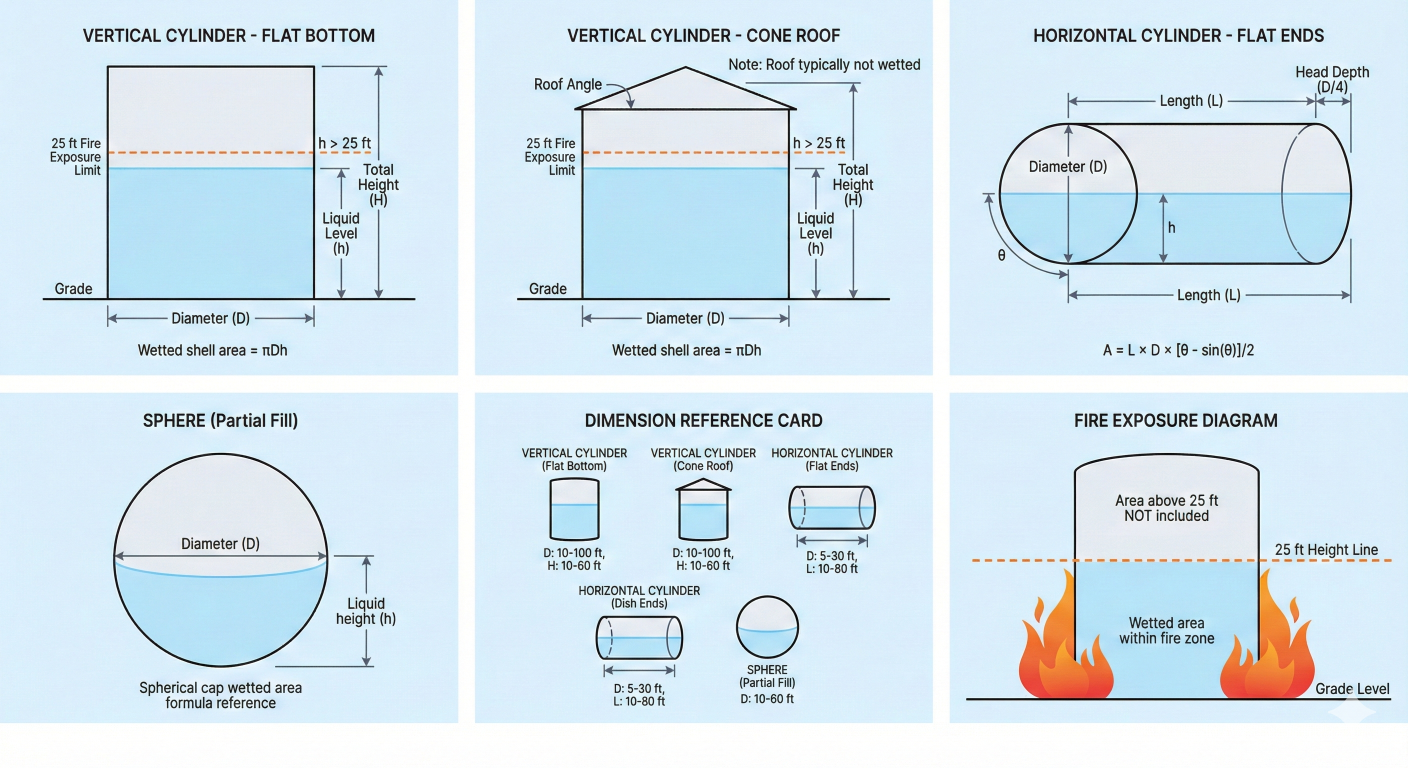
Tank Configuration
Blow-By Gas Source
psig
Cv
in (ID)
ft
in
Gas Properties
°F
Typical Tank Pressure Ratings
API 650 (standard)1 oz/in²
API 650 Annex F2.5–15 psig
Low-pressure tanks0.5–1.0 psig
Learn the Theory
API 2000 methodology, thermal breathing, blow-by scenarios, and emergency venting
Engineering Basis
Blow-By Scenario (PHA)
Vent Area = Q × √(SG × T) / (C × K × P)
Gas flow from failed-open control valve through restriction orifice to atmospheric tank. Critical for tank vent sizing.
API 2000 Thermal Inbreathing
V_IT = C × (V_tk)^0.7 × R_i
Thermal contraction during cooling. C depends on vapor pressure, latitude, and storage temp.
Design Limits
API 650 P/V vent
1 oz/in²
Vent velocity max
120 ft/s
API 2000 limit
15 psig
Emergency factor
2× normal
PHA Blow-By Scenario
Common scenario in PHAs: control valve on vessel sump fails open, allowing upstream gas to blow through restriction orifice to condensate tank. Size tank vent to handle this gas flow.