Water volume calculations are essential for pipeline hydrotesting, tank gauging, and operational planning. Accurate volumes ensure proper test pressures, adequate water supply, and correct inventory measurements.
Hydrotesting
Pipeline integrity
ASME B31.4/B31.8 require hydrostatic testing to verify pipeline strength.
Tank gauging
Inventory control
API 2550 strapping tables convert tank level to volume.
Operations
Logistics planning
Water truck loads, disposal volumes, and storage sizing.
Water Properties at 60°F
Property
Value
Reference
Density
62.37 lb/ft³
API MPMS 11.1
Specific gravity
0.999
Relative to 4°C water
Weight per gallon
8.34 lb/gal
US gallon
Weight per barrel
350 lb/bbl
42-gallon oil barrel
2. Volume Formulas
Pipeline Volume
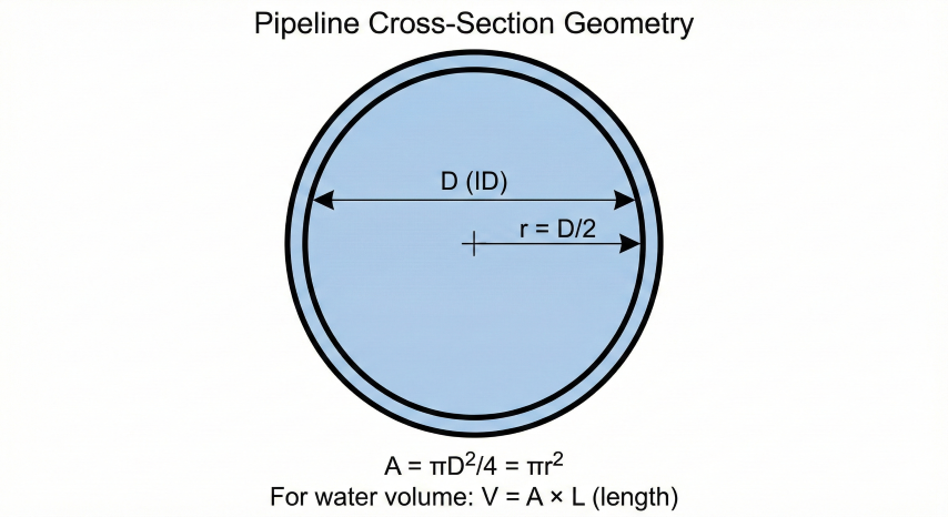
Pipeline internal volume is calculated as a simple cylinder using the inside diameter.
Pipeline Volume Formula:
V = π × (D/24)² × L
Where:
V = Volume (ft³)
D = Inside diameter (inches)
L = Length (feet)
24 = Converts diameter in inches to radius in feet (D/2/12)
In gallons: V_gal = V × 7.48052
In barrels: V_bbl = V × 0.1781
Example - 12" pipeline, 1 mile (5,280 ft):
V = π × (12/24)² × 5,280
V = 3.1416 × 0.25 × 5,280 = 4,147 ft³
V_gal = 4,147 × 7.48 = 31,024 gallons
V_bbl = 4,147 × 0.1781 = 739 barrels
Weight = 4,147 × 62.4 = 258,773 lbs
Pipeline cross-section geometry showing diameter, radius, and internal flow area for volume calculations.
Vertical Cylindrical Tank
Vertical tanks (API 650) use the same cylinder formula, with liquid height determining partial fill volume.
Vertical Tank Volume:
V = π × r² × h
Where:
r = Tank radius (ft) = diameter / 2
h = Liquid height (ft)
Total capacity uses full tank height.
Working capacity excludes freeboard (6-12") and heel.
Example - 20 ft diameter × 30 ft tall:
r = 10 ft
V_total = π × 10² × 30 = 9,425 ft³ = 70,500 gal = 1,679 bbl
With 2 ft freeboard + 1 ft heel:
V_working = π × 10² × 27 = 8,483 ft³ = 63,450 gal
Horizontal Cylindrical Tank (Partial Fill)
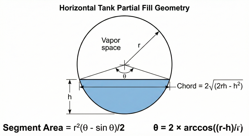
Horizontal tanks require the circular segment formula for partial fill calculations. This is the standard method per API 2550.
Horizontal Tank Partial Fill Formula:
For liquid height h from bottom of tank:
θ = 2 × arccos((r - h) / r) [central angle in radians]
A = (r²/2) × (θ - sin(θ)) [circular segment area]
V = A × L [volume = area × length]
Where:
r = Tank radius (ft)
h = Liquid height from bottom (ft)
L = Tank length (ft)
Special cases:
Half full (h = r): V = π × r² × L / 2
Full (h = 2r): V = π × r² × L
Example - 10 ft diameter × 40 ft long, 6 ft liquid level:
r = 5 ft, h = 6 ft, L = 40 ft
θ = 2 × arccos((5-6)/5) = 2 × arccos(-0.2) = 2 × 1.772 = 3.544 rad
A = (25/2) × (3.544 - sin(3.544)) = 12.5 × (3.544 - (-0.355)) = 48.7 ft²
V = 48.7 × 40 = 1,950 ft³ = 14,590 gal = 347 bbl (62% full)
Horizontal tank partial fill geometry showing radius, liquid height, central angle, and circular segment area for volume calculation.
Rectangular Tank
Rectangular Tank Volume:
V = L × W × h
Where:
L = Length (ft)
W = Width (ft)
h = Liquid height (ft)
Example - 40 ft × 20 ft × 10 ft tank at 8 ft level:
V = 40 × 20 × 8 = 6,400 ft³ = 47,875 gal = 1,140 bbl
Percent full = 8/10 = 80%
3. Unit Conversions
Volume Unit Conversions
From
To Gallons
To Barrels
To ft³
To Liters
1 Gallon
1
0.02381
0.1337
3.785
1 Barrel
42
1
5.615
159.0
1 ft³
7.481
0.1781
1
28.32
1 m³
264.2
6.290
35.31
1,000
Pipeline Volume per Unit Length
Quick reference for common pipe sizes (standard wall):
NPS (in)
ID (in)
gal/ft
bbl/mile
lb water/ft
4
4.026
0.661
83
5.5
6
6.065
1.501
189
12.5
8
7.981
2.599
327
21.7
10
10.020
4.098
515
34.2
12
12.000
5.875
739
49.0
16
15.000
9.180
1,154
76.6
20
19.000
14.73
1,852
122.9
24
23.000
21.59
2,715
180.1
30
29.000
34.31
4,314
286.2
36
35.000
49.98
6,285
416.9
Water truck capacity: Standard water trucks hold 110-130 barrels (4,620-5,460 gallons). For hydrotest planning, divide total volume by 130 bbl to estimate truck loads required.
4. Hydrostatic Testing
Hydrostatic testing verifies pipeline integrity by pressurizing with water. Requirements vary by code and class location.
Test Pressure Requirements
Code
Application
Test Pressure
Duration
ASME B31.4
Liquid pipelines
1.25 × MAOP
4 hours minimum
ASME B31.8 Class 1
Gas, rural areas
1.1 × MAOP
8 hours
ASME B31.8 Class 2
Gas, suburban
1.25 × MAOP
8 hours
ASME B31.8 Class 3-4
Gas, urban/HCA
1.4-1.5 × MAOP
8 hours
API 1104
Weld qualification
Per design spec
Per procedure
Water Volume Planning
Hydrotest Water Requirements:
Total water needed = Fill volume + Test makeup + Purge volume
Fill volume: Calculated pipeline volume (use calculator)
Test makeup: 1-3% for compression and leak testing
Purge volume: 2-3× pipeline volume for post-test purging
Rule of thumb:
Plan for 1.5× pipeline volume total water availability
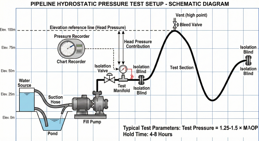
Elevation considerations:
Head pressure = 0.433 psi/ft × elevation change (water)
For hilly terrain:
P_test (low point) = P_test (specified) + (0.433 × Δh)
May exceed pipe rating - consider segmented tests
Hydrostatic pressure test configuration showing water source, fill equipment, test section with isolation, and elevation profile affecting head pressure.
Dissolved oxygen: < 1 ppm preferred, or add oxygen scavenger
pH: 6.5-8.5 neutral range
Bacteria: Biocide treatment for extended holds (> 7 days)
Temperature: Above freezing, below 120°F
Post-test considerations: Water must be disposed properly. Options include evaporation ponds, injection wells (UIC Class II), municipal treatment (if clean), or trucking to disposal facility. Document water quality and disposal method.
5. Practical Examples
Example 1: Pipeline Hydrotest Planning
Given:
- 16" NPS pipeline, 0.375" wall (ID = 15.25")
- Length: 15 miles
- MAOP: 1,000 psig
- Terrain: 200 ft elevation gain
Calculate water requirements:
1. Pipeline volume:
V = π × (15.25/24)² × (15 × 5,280) = 31,840 ft³
V = 238,200 gal = 5,671 bbl
2. Truck loads required:
5,671 bbl ÷ 130 bbl/truck = 44 truck loads
3. Water weight:
31,840 ft³ × 62.4 lb/ft³ = 1,987,000 lbs = 994 tons
4. Head pressure at low point:
ΔP = 0.433 × 200 ft = 87 psi additional
5. Test pressure:
P_test = 1.25 × 1,000 = 1,250 psig (high point)
P_test = 1,250 + 87 = 1,337 psig (low point)
6. Total water planning:
Fill + margin = 5,671 × 1.5 = 8,500 bbl available
Plan for 66 truck loads
Example 2: Tank Inventory Calculation
Given:
- Horizontal tank: 10 ft diameter × 30 ft long
- Gauge reading: 7.5 ft liquid level
Calculate volume:
1. Tank parameters:
r = 5 ft, L = 30 ft, h = 7.5 ft
2. Central angle:
θ = 2 × arccos((5-7.5)/5) = 2 × arccos(-0.5)
θ = 2 × 2.094 = 4.189 radians
3. Segment area:
A = (25/2) × (4.189 - sin(4.189))
A = 12.5 × (4.189 - (-0.866)) = 63.2 ft²
4. Volume:
V = 63.2 × 30 = 1,896 ft³ = 14,180 gal = 338 bbl
5. Percent full:
Full capacity = π × 25 × 30 = 2,356 ft³
Percent = 1,896/2,356 = 80.5%
Standard Tank Capacities (API 650)
Diameter (ft)
Height (ft)
Capacity (bbl)
Capacity (gal)
10
16
224
9,408
15
24
751
31,542
20
32
1,498
62,916
30
40
4,209
176,778
50
48
14,027
589,134
Common pitfalls: (1) Using OD instead of ID for pipe volume - can cause 10%+ error. (2) Forgetting elevation effects on test pressure. (3) Underestimating water needs - plan for 1.5× fill volume. (4) Not accounting for freeboard/heel in tank working capacity.