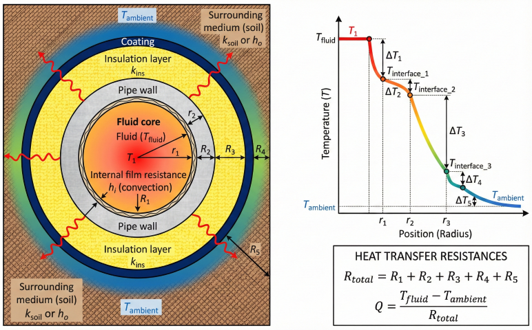
1. Heat Transfer Fundamentals
Fluid temperature changes along a pipeline due to heat exchange with surroundings. For hot fluids, temperature drops; for cold fluids (below ambient), temperature rises toward equilibrium.
Heat Transfer Mechanisms
- Convection (internal): Fluid to pipe wall—depends on flow regime and fluid properties
- Conduction: Through pipe wall, insulation, and soil (if buried)
- Convection (external): Pipe surface to air (above-ground) or conduction to soil
- Radiation: Usually minor for pipelines at moderate temperatures
Key Parameters
| Parameter | Symbol | Units |
|---|---|---|
| Overall heat transfer coefficient | U | BTU/hr·ft²·°F |
| Thermal conductivity | k | BTU/hr·ft·°F |
| Convection coefficient | h | BTU/hr·ft²·°F |
| Mass flow rate | ṁ | lb/hr |
| Specific heat | Cp | BTU/lb·°F |
2. Overall Heat Transfer Coefficient
The overall U-value combines all thermal resistances in series from fluid to surroundings.
General Equation
Thermal Conductivity Values
| Material | k (BTU/hr·ft·°F) |
|---|---|
| Carbon steel | 26–30 |
| Stainless steel | 8–10 |
| Calcium silicate insulation | 0.032–0.045 |
| Mineral wool | 0.023–0.030 |
| Polyurethane foam | 0.012–0.018 |
| Dry soil | 0.15–0.25 |
| Wet soil | 0.6–1.0 |
| Saturated soil | 1.0–1.5 |
Convection Coefficients
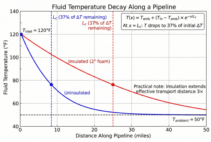
3. Temperature Profile Equations
Temperature varies exponentially along the pipeline, approaching ambient asymptotically.
Steady-State Temperature Profile
Heat Loss Rate
4. Buried Pipeline Calculations
For buried pipelines, soil thermal resistance replaces external convection. Burial depth significantly affects heat transfer.
Soil Thermal Resistance
Buried Pipeline U-Value
Ground Temperature
| Depth (ft) | Temperature Variation |
|---|---|
| Surface | Follows air temperature |
| 3–4 | ±15°F seasonal swing |
| 6–8 | ±5°F seasonal swing |
| > 15 | Nearly constant (≈ annual mean air temp) |
5. Joule-Thomson Cooling at Pressure Reduction
Unlike gradual heat loss along a pipeline, Joule-Thomson (J-T) cooling occurs instantaneously at pressure reduction points—control valves, regulators, chokes, and orifice plates. This isenthalpic expansion causes significant temperature drops that can trigger hydrate formation.
The Joule-Thomson Effect
When gas expands through a throttling device with no heat exchange (isenthalpic process), temperature changes due to intermolecular forces. For most gases at typical pipeline conditions, expansion causes cooling.
Rigorous J-T Coefficient Calculation
The calculator uses peer-reviewed correlations for accurate J-T coefficient estimation based on reduced temperature and pressure.
| Property | Correlation | Reference |
|---|---|---|
| Pseudo-critical temperature | T_pc = 169.2 + 349.5×SG - 74.0×SG² | Sutton (1985) |
| Pseudo-critical pressure | P_pc = 756.8 - 131.0×SG - 3.6×SG² | Sutton (1985) |
| J-T coefficient function | f(Pr,Tr) = 2.343×Tr^(-2.04) - 0.071×Pr + 0.0568 | ACS Omega (2021) |
Step-Wise Integration
For large pressure drops (>150 psi), the J-T coefficient varies significantly. The calculator uses step-wise integration:
- Divide total ΔP into 50 psi increments
- Recalculate μ_JT at each step using updated T and P
- Sum temperature drops: ΔT_total = Σ(μ_JT,i × ΔP_step)
This approach improves accuracy for large pressure drops from regulators or choke valves.
Hydrate Temperature Prediction
Hydrates form when gas temperature drops below the hydrate equilibrium temperature. The calculator averages two industry correlations:
| Correlation | Equation | Valid Range |
|---|---|---|
| Katz (1945) | T_hyd = -54.5 + 13.1×ln(P) + 40×γ | 0.6 < SG < 0.9 |
| Towler-Mokhatab (2005) | T_hyd = 13.47×ln(P) + 34.27×ln(γ) - 1.675×ln(P)×ln(γ) - 20.35 | Modern refinement |
Example: Pressure Regulation Station
Given: Natural gas (SG=0.65), P1=800 psia, T1=80°F, P2=250 psia
Step 1: Pseudo-critical properties
T_pc = 169.2 + 349.5(0.65) - 74.0(0.65)² = 365°R
P_pc = 756.8 - 131.0(0.65) - 3.6(0.65)² = 670 psia
Step 2: J-T coefficient (at inlet)
Tr = 540°R / 365°R = 1.48
Pr = 800 / 670 = 1.19
Cp = 0.48 BTU/lb·°F
f(Pr,Tr) = 2.343(1.48)^(-2.04) - 0.071(1.19) + 0.0568 = 1.03
μ_JT = (365/670) × 1.03 / 0.48 × 0.058 = 0.068°F/psi
Step 3: Temperature drop (step-wise)
ΔP = 550 psi (11 steps of 50 psi)
ΔT_total ≈ 42°F (varies through integration)
T_downstream = 80 - 42 = 38°F
Step 4: Hydrate check
T_hydrate @ 250 psia ≈ 44°F (Katz + Towler avg)
Margin = 38 - 44 = -6°F (HYDRATE RISK!)
Pure Component J-T Coefficients
For pure gases and non-hydrocarbon components, the calculator uses published J-T coefficients from GPSA and Katz. The rigorous correlation above is used only for natural gas mixtures (SG 0.55–0.85).
| Gas | μ_JT (°F/psi) | Notes |
|---|---|---|
| Methane (C₁) | 0.072 | Primary NG component |
| Ethane (C₂) | 0.105 | Higher MW = larger effect |
| Propane (C₃) | 0.095 | Moderate J-T effect |
| Nitrogen (N₂) | 0.015 | Low J-T effect |
| Carbon Dioxide (CO₂) | 0.028 | Acid gas component |
| Air | 0.025 | Reference gas |
| Hydrogen (H₂) | -0.005 | Heats on expansion (inverts) |
6. Applications
Why Temperature Matters
- Hydrate formation: Low temperatures in wet gas cause hydrate plugs
- Wax deposition: Crude oil below WAT (wax appearance temp) deposits paraffin
- Viscosity increase: Heavy oil becomes difficult to pump when cold
- Two-phase flow: Condensation changes flow regime and pressure drop
- Thermal stress: Temperature changes cause pipe expansion/contraction
Example Calculation
Given: 12" insulated buried gas pipeline, 50 miles, inlet 120°F, ground temp 55°F, flow 100 MMSCFD, U = 0.10 BTU/hr·ft²·°F
Step 1: Mass flow rate
ṁ = 100×10⁶ × 0.044 lb/scf / 24 hr = 183,000 lb/hr
Step 2: Characteristic length
Cp = 0.55 BTU/lb·°F, D = 1 ft
L_c = (183,000 × 0.55) / (0.10 × π × 1)
L_c = 320,000 ft = 61 miles
Step 3: Outlet temperature
L = 50 miles = 264,000 ft
T_out = 55 + (120-55) × exp(-264,000/320,000)
T_out = 55 + 65 × 0.44 = 55 + 29 = 84°F
Step 4: Heat loss
Q = 183,000 × 0.55 × (120-84) = 3.7 MM BTU/hr
Temperature Maintenance Options
| Method | Application |
|---|---|
| Insulation | Reduce heat loss, slow cooling rate |
| Electric heat tracing | Maintain minimum temp, prevent freezing |
| Steam tracing | Process plants, short runs |
| Hot oil/water circulation | Subsea flowlines, heavy oil |
| Direct electrical heating (DEH) | Subsea pipelines |
References
- GPSA, Sections 13, 17, 20
- Holman, J.P. – Heat Transfer
- API RP 14E – Offshore Production Platform Piping Systems
- ASME B31.4 / B31.8 – Pipeline Transportation Systems
- Sutton, R.P. (1985) – "Compressibility Factors for High-Molecular-Weight Reservoir Gases", SPE 14265
- ACS Omega (2021) – "Joule-Thomson Coefficient Correlation for Natural Gas"
- Katz, D.L. (1945) – "Prediction of Conditions for Hydrate Formation in Natural Gases"
- Towler, B.F. & Mokhatab, S. (2005) – "Quickly Estimate Hydrate Formation Conditions in Natural Gases"
Ready to use the calculator?
→ Launch Calculator