Design mechanical refrigeration systems using vapor-compression cycles, propane and ethylene refrigerants, compressor-condenser-evaporator equipment, COP optimization, and cascade systems for cryogenic applications.
Mechanical refrigeration systems use the vapor-compression cycle to transfer heat from a low-temperature process stream to ambient conditions. Essential for cryogenic gas processing, LNG production, and petrochemical operations.
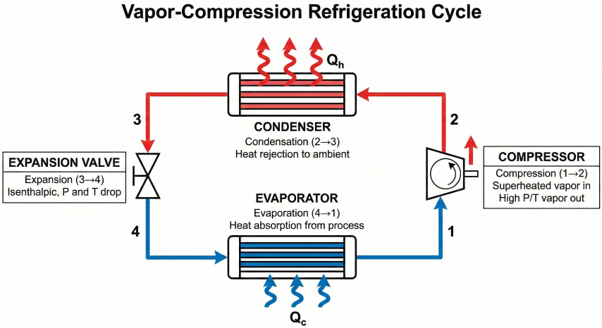
Vapor-compression refrigeration cycle schematic showing the four main components and thermodynamic state points.
NGL recovery
Gas plant chilling
Propane refrigeration cools inlet gas to -20°F to -40°F for ethane+ recovery.
LNG production
Multi-stage cascade
Propane, ethylene, methane cascade to liquefy natural gas at -260°F.
Gas dew pointing
Pipeline spec conditioning
Mechanical refrigeration to meet -20°F hydrocarbon dew point at 800 psia.
Ethylene plants
Cryogenic separation
Multi-level refrigeration for ethylene/ethane splitter at -150°F to -100°F.
Refrigeration vs Expander Cooling
Method
Temperature Range
Efficiency
Applications
Mechanical refrigeration
-150°F to +40°F
COP = 2-4 (1 HP removes 2-4 HP of heat)
Reliable, flexible, good for variable loads
Turboexpander (JT valve)
-200°F to -50°F
η = 80-88% isentropic efficiency
Gas processing, no external power, recovers work
Hybrid (expander + refrigeration)
-150°F to -40°F
Combined benefits
Deep NGL recovery, optimize expander + propane refrigeration
Refrigeration Load Sources
Total refrigeration duty is the sum of all heat loads that must be removed:
Process cooling load: Cool gas from 100°F to -40°F (sensible heat + latent heat if condensing)
Demethanizer reboiler: Evaporate bottom product using refrigerant evaporator
Subcooling reflux: Subcool overhead liquid reflux before returning to column
Heat leak: Heat ingress through insulation, pipe flanges, valves (1-5% of total duty typical)
Pump work: Liquid pumps add heat to process (W_pump / η_pump)
Why refrigeration matters: Refrigeration is typically 20-40% of total operating cost in cryogenic gas plants and LNG facilities. A 1% improvement in COP (coefficient of performance) can save $100,000-500,000/year in power costs for a 100 MMscfd gas plant. Proper design optimizes equipment size, refrigerant selection, and operating conditions.
2. Vapor-Compression Refrigeration Cycle
The basic refrigeration cycle consists of four processes: compression, condensation, expansion, and evaporation.
Ideal Cycle (Carnot Efficiency)
Carnot COP (Theoretical Maximum):
COP_Carnot = T_cold / (T_hot - T_cold)
Where:
T_cold = Evaporator temperature (absolute, °R or K)
T_hot = Condenser temperature (absolute, °R or K)
Example:
Evaporator at -40°F = 420°R
Condenser at 100°F = 560°R
COP_Carnot = 420 / (560 - 420) = 420 / 140 = 3.0
Carnot COP is theoretical maximum (reversible cycle).
Real cycles achieve 40-70% of Carnot efficiency due to:
- Compressor inefficiency
- Pressure drops in piping/heat exchangers
- Temperature differences in evaporator/condenser
- Superheat and subcooling
Standard Vapor-Compression Cycle
The practical cycle consists of four components operating in a closed loop:
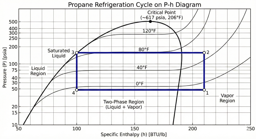
Propane refrigeration cycle plotted on pressure-enthalpy diagram showing thermodynamic state points and processes.
Cycle States (clockwise on P-h diagram):
State 1 → 2: Compression (isentropic ideal, polytropic real)
- Inlet: Saturated or superheated vapor at evaporator pressure
- Outlet: Superheated vapor at condenser pressure
- Work input: W_comp = m × (h₂ - h₁) / η_comp
State 2 → 3: Condensation (isobaric)
- Cool superheated vapor to saturated vapor (desuperheat)
- Condense vapor to saturated liquid
- Subcool liquid below saturation (optional)
- Heat rejection: Q_cond = m × (h₂ - h₃)
State 3 → 4: Expansion (isenthalpic, h₃ = h₄)
- Throttle high-pressure liquid to low pressure
- Flash evaporation creates two-phase mixture
- No work recovered (in basic cycle)
State 4 → 1: Evaporation (isobaric)
- Two-phase mixture evaporates to saturated vapor
- Absorbs heat from process stream
- Refrigeration effect: Q_evap = m × (h₁ - h₄)
Performance Metrics:
COP = Q_evap / W_comp = (h₁ - h₄) / (h₂ - h₁)
Refrigeration tons = Q_evap / 12,000 Btu/hr (1 ton = 3.517 kW)
Compressor power (HP) = W_comp / 2545 Btu/hr
Application: Cascade systems, very low evaporator temperatures (< -80°F)
COP optimization: COP increases with higher evaporator temperature and lower condenser temperature. Every 10°F reduction in lift (T_cond - T_evap) improves COP by 10-15%. Minimize approach temperatures in heat exchangers (5-10°F typical), use economizers for large systems, and optimize condenser cooling (water vs air).
3. Compressor, Condenser, and Evaporator Design
Compressor Selection
Compressor Type
Capacity Range
Efficiency
Applications
Reciprocating (piston)
10-2000 HP
η_isen = 0.70-0.80
Small/medium plants, high compression ratios, multiple stages
Screw (rotary)
50-3000 HP
η_isen = 0.65-0.75
Medium plants, smooth operation, oil-flooded or oil-free
Centrifugal
500-40,000 HP
η_isen = 0.75-0.85
Large LNG plants, high flow rates, low compression ratios
Scroll
1-50 HP
η_isen = 0.65-0.72
Small HVAC, skid-mounted packages
Compressor Sizing
Volumetric Flow Rate (Inlet):
ICFM = (m / ρ₁) × 60 (inlet cubic feet per minute)
Where:
m = Mass flow rate (lb/s)
ρ₁ = Suction density (lb/ft³)
Compression Ratio:
r = P_discharge / P_suction
Design limits:
Single-stage reciprocating: r < 8-10
Single-stage screw: r < 10-15
Single-stage centrifugal: r < 3-4
For higher ratios, use multi-stage compression.
Discharge Temperature:
T₂ / T₁ = (P₂ / P₁)^((k-1)/k) (isentropic)
Where k = Cp/Cv ≈ 1.13 for propane, 1.22 for ethylene
For real compression:
T₂ = T₁ × [1 + (1/η_isen) × ((P₂/P₁)^((k-1)/k) - 1)]
Limit discharge temperature:
T₂ < 250-300°F to prevent oil breakdown (reciprocating/screw)
T₂ < 300-350°F for ethylene (no oil concerns in centrifugal)
Condenser Design
Condensers reject heat from hot refrigerant vapor to cooling medium (air or water):
Air-Cooled Condensers
Heat Transfer Area:
A = Q / (U × LMTD)
Where:
Q = Condenser duty (Btu/hr)
U = Overall heat transfer coefficient (Btu/hr·ft²·°F)
Typical U = 15-25 for air-cooled finned tube
LMTD = Log mean temperature difference
LMTD Calculation:
For condensation (isothermal on refrigerant side):
T_ref = Condensing temperature (constant)
T_air,in = Ambient air temperature
T_air,out = Air outlet temperature
ΔT₁ = T_ref - T_air,in
ΔT₂ = T_ref - T_air,out
LMTD = (ΔT₁ - ΔT₂) / ln(ΔT₁/ΔT₂)
Design Approach:
Typical approach: T_ref - T_air,in = 15-25°F
Example:
Ambient air = 95°F → Condensing temp = 110-120°F → P_cond = 210-250 psia (propane)
Fan power:
P_fan = (CFM × ΔP) / (6356 × η_fan) (HP)
Typical CFM = 1500-2500 cfm per ton of refrigeration
Water-Cooled Condensers
Shell-and-Tube Condenser:
Refrigerant condenses on shell side (horizontal or vertical)
Cooling water flows through tubes
U = 100-200 Btu/hr·ft²·°F (much higher than air-cooled)
Design approach: T_ref - T_water,out = 5-10°F
Cooling Water Flow Rate:
m_water = Q / (Cp × ΔT)
Where:
Q = Condenser duty (Btu/hr)
Cp = 1.0 Btu/lb·°F (water)
ΔT = T_out - T_in (typically 10-20°F rise)
Example:
Q = 10 MMBtu/hr, ΔT = 15°F
m_water = 10,000,000 / (1.0 × 15) = 667,000 lb/hr = 1340 gpm
Fouling factor: Add 0.001-0.002 (hr·ft²·°F/Btu) for cooling tower water
Evaporator Design
Evaporators absorb heat from process stream to cold refrigerant:
Equipment sizing tradeoffs: Larger heat exchangers (more area, smaller ΔT_min) reduce required refrigerant lift → higher COP → lower compressor power. But larger exchangers cost more capital. Typical economic optimum: ΔT_min = 5-10°F for process gas cooling, 10-15°F for reboilers. For LNG plants with 20+ year life, invest in low ΔT_min (3-5°F) to minimize power costs.
4. Refrigerant Selection
Refrigerant choice depends on required temperature range, thermophysical properties, safety, environmental impact, and cost.
NGL recovery, gas dew pointing, LNG (flammable, excellent properties)
Ethylene (R-1150, C₂H₄)
-150 to -40
870 @ 0°F
Deep NGL recovery, ethylene plants, LNG cascade (flammable)
Methane (R-50, CH₄)
-260 to -150
Very high
LNG final stage, cryogenic applications (flammable, high pressure)
R-134a (HFC)
-20 to +60
136
HVAC, small industrial (non-flammable, low toxicity, GWP=1430)
R-404A (HFC blend)
-40 to +50
215
Commercial refrigeration, cold storage (non-flammable, high GWP=3922)
Refrigerant Properties Comparison
Key Properties (at typical evaporator conditions):
Propane at -40°F evaporator, 100°F condenser:
P_evap = 14.2 psia, P_cond = 190 psia
Latent heat λ = 131 Btu/lb
Compression ratio r = 13.4
Ideal COP ≈ 2.8-3.2
Ethylene at -100°F evaporator, 80°F condenser:
P_evap = 37 psia, P_cond = 630 psia
Latent heat λ = 183 Btu/lb
Compression ratio r = 17
Ideal COP ≈ 2.2-2.8 (lower due to larger lift)
Ammonia at -40°F evaporator, 100°F condenser:
P_evap = 10.4 psia, P_cond = 247 psia
Latent heat λ = 565 Btu/lb (highest of common refrigerants)
Compression ratio r = 23.7
Ideal COP ≈ 2.8-3.3
R-134a at -20°F evaporator, 100°F condenser:
P_evap = 12.2 psia, P_cond = 136 psia
Latent heat λ = 84 Btu/lb
Compression ratio r = 11.1
Ideal COP ≈ 2.4-3.0
Hydrocarbon Refrigerants in Oil & Gas
Propane and ethylene dominate oil/gas applications despite flammability:
Advantages of Hydrocarbon Refrigerants
Excellent thermodynamic properties: High latent heat, low compression ratio, good COP
Already present in facility: Propane/ethylene available from process streams, no import needed
Low cost: Propane $0.50-1.50/gal vs R-404A $5-15/lb
Environmental: GWP ≈ 3-5 (vs 1000-4000 for HFCs), zero ODP
Compatibility: Compatible with mineral oils, metals, elastomers
Safety Considerations
Flammability: LEL 2.1% for propane, design per API RP 521 for flammable fluid handling
Ventilation: Equipment in well-ventilated areas, gas detection, isolation valves
Electrical classification: Class I, Division 2 hazardous area (or Division 1 near potential leak sources)
Fire protection: Water deluge system for compressor area, emergency shutdown systems
Inventory minimization: Use compact heat exchangers (plate-fin) to reduce refrigerant inventory
Refrigerant selection for gas processing: Propane is standard for -50°F to 0°F applications (NGL recovery, dew pointing). Ethylene for -150°F to -50°F (deep NGL, ethane rejection). Ammonia for HVAC and cold storage (excellent properties but toxic). HFCs being phased out due to high GWP (Montreal Protocol, Kigali Amendment). Future: Low-GWP alternatives (R-1234yf, CO₂, natural refrigerants).
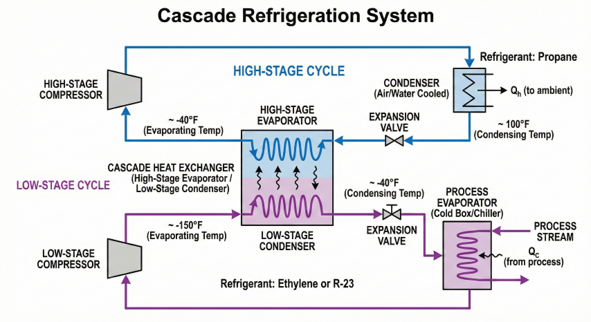
5. Cascade Refrigeration Systems
Cascade systems use two or more refrigeration cycles in series, with the condenser of the low-temperature cycle rejecting heat to the evaporator of the high-temperature cycle. Essential for cryogenic applications.
Why Cascade?
Single-stage compression becomes impractical for large temperature lifts due to:
High compression ratio: For propane, -150°F evaporator and 100°F condenser → r = 50+ (excessive)
Low volumetric efficiency: High compression ratio → large clearance volume losses
Poor COP: Efficiency drops sharply with compression ratio > 10-15
Two-Stage Cascade Configuration
Cascade refrigeration system with propane high-stage and ethylene low-stage cycles connected by cascade heat exchanger.
Typical LNG Cascade:
High-temperature stage (warm loop):
Refrigerant: Propane (C₃)
Evaporator: -40°F to 0°F
Condenser: 80-100°F (air or water cooled)
Process duty: Cool feed gas, condense NGLs
Low-temperature stage (cold loop):
Refrigerant: Ethylene (C₂)
Evaporator: -120°F to -100°F
Condenser: -50°F to -40°F (cooled by propane evaporator)
Process duty: Subcool LNG, demethanizer reboiler
Cascade heat exchanger:
Propane evaporator = Ethylene condenser
ΔT_approach = 5-10°F
Overall COP:
COP_cascade = Q_evap,cold / (W_comp,hot + W_comp,cold)
Typically COP_cascade = 1.8-2.5 (lower than single-stage due to two compression stages)
But this enables temperature ranges impossible for single-stage.
Three-Stage Cascade for LNG
Large LNG plants use propane-ethylene-methane cascade to reach -260°F:
Stage
Refrigerant
Evaporator Temp
Process Duty
1 (warm)
Propane (C₃)
-40°F to +10°F
Pre-cool feed gas, remove heavy HCs
2 (intermediate)
Ethylene (C₂)
-140°F to -60°F
Liquefy methane, sub-cool LNG
3 (cold)
Methane (C₁)
-260°F to -200°F
Final LNG sub-cooling, nitrogen rejection
Mixed Refrigerant (MR) Alternative
Single mixed-refrigerant cycle uses blend of components (N₂, CH₄, C₂H₆, C₃H₈) instead of pure refrigerants:
Mixed Refrigerant Composition (typical):
Nitrogen (N₂): 5-10 mol%
Methane (CH₄): 40-50%
Ethane (C₂H₆): 20-30%
Propane (C₃H₈): 15-25%
How it works:
Mixture condenses over temperature range (not isothermal)
- Propane condenses first at -40°F
- Ethane condenses at -80°F
- Methane condenses at -150°F
- Nitrogen remains vapor
Temperature glide during condensation matches process cooling curve
→ Better thermodynamic efficiency than cascade (smaller ΔT_min)
After expansion, mixture evaporates in reverse order:
- Light components (N₂, CH₄) evaporate first at cold end (-260°F)
- Heavy components (C₃) evaporate last at warm end (-40°F)
Advantages vs Cascade:
- 10-20% higher COP (better temperature matching)
- Simpler: single compressor loop (but multi-stage compression)
- Lower capital cost for large LNG plants
Disadvantages:
- Complex composition control (makeup, bleed)
- Sensitive to composition changes
- Requires rigorous simulation (Aspen HYSYS, ProMax)
Cascade vs Mixed Refrigerant Selection
Application
Preferred System
Reason
Small NGL plant (< 50 MMscfd)
Single-stage propane
Simple, reliable, -40°F adequate
Deep NGL recovery (90%+ C2)
Propane/ethylene cascade
-100°F to -120°F required, proven technology
Small LNG (< 1 MTPA)
Propane/ethylene cascade
Simpler operation, easier composition control
Large LNG (> 3 MTPA)
Mixed refrigerant (single or dual MR)
10-15% efficiency gain justifies complexity at scale
Offshore LNG (FLNG)
Nitrogen-expander or single MR
Weight/space constraints favor compact systems
LNG Plant Refrigeration Power
Specific Power Consumption:
Modern LNG plants: 0.25-0.35 kWh/kg LNG
For 5 MTPA LNG plant:
Production rate = 5,000,000 MT/yr / (8760 hr/yr) = 570 MT/hr = 570,000 kg/hr
Power consumption = 570,000 kg/hr × 0.30 kWh/kg = 171,000 kW = 171 MW
Compressor drivers:
- Gas turbines (aeroderivative or heavy-duty)
- Electric motors (if grid power available)
Fuel cost at $3/MMBtu, heat rate 10,000 Btu/kWh:
Fuel cost = 171 MW × 10,000 Btu/kWh × $3/MMBtu / 1000 = $5.1 million/hr
→ $45 million/year continuous operation
1% efficiency improvement saves $450,000/year in fuel.
Cascade system design: Use two-stage cascade (propane/ethylene) for gas processing down to -150°F. Use three-stage cascade or mixed refrigerant for LNG production (-260°F). Optimize inter-stage temperatures to balance compression ratios (geometric mean: T_mid = √(T_cold × T_hot) on absolute scale). Size cascade heat exchangers with 5-10°F approach to minimize exergy destruction. For large LNG, evaluate MR vs cascade based on capital cost, operating cost, and reliability.