1. ASME B16.5 Flange Classes
ASME B16.5 defines seven standard pressure classes. The class number is not the pressure rating—it's a dimensionless designation. Actual ratings depend on material and temperature.
| Class | Rating @ 100°F (Group 1.1) |
Typical Use |
|---|---|---|
| 150 | 285 psig | Low-pressure water, HVAC, process utilities |
| 300 | 740 psig | Steam systems, gas distribution |
| 400 | 990 psig | Intermediate service (less common) |
| 600 | 1,480 psig | High-pressure gas, oil pipelines, refineries |
| 900 | 2,220 psig | Injection wells, high-pressure process |
| 1500 | 3,705 psig | Extreme pressure applications |
| 2500 | 6,170 psig | Ultra-high pressure, specialty systems |
Key point: A Class 150 flange is rated for 285 psig at ambient—not 150 psig. The class number is historical nomenclature, not a pressure value.
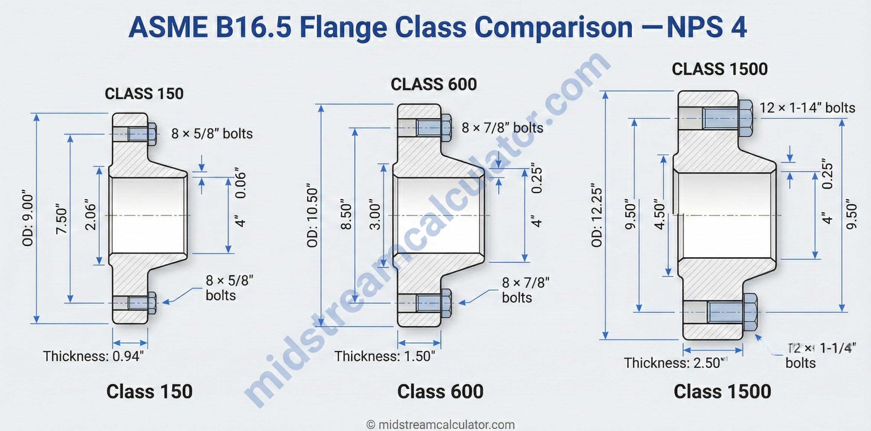
Physical Differences by Class
Higher classes have thicker walls, more bolts, larger bolt diameters, and larger bolt circles. Flange facing also varies: raised face (RF) is standard for most classes; ring-type joint (RTJ) is used for Class 600+ in critical service.
Not interchangeable: Flanges of different classes cannot mate—bolt patterns, facing dimensions, and thicknesses differ. Always match classes across a joint.
2. Pressure-Temperature Ratings
Material strength decreases at elevated temperatures. ASME B16.5 provides pressure-temperature (P-T) tables showing maximum allowable working pressure at each temperature for every material group and class.
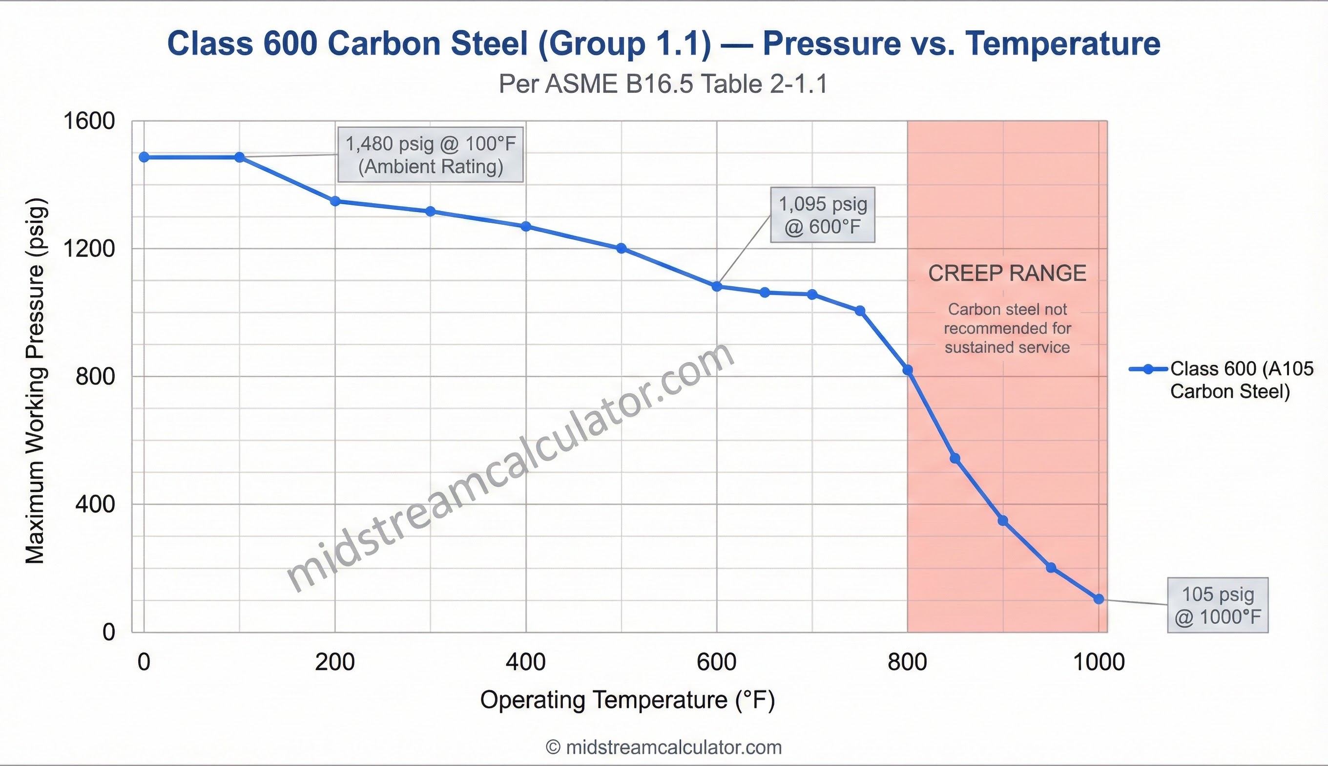
Carbon Steel P-T Ratings (Group 1.1)
Values per ASME B16.5 Table 2-1.1 for ASTM A105, A216 WCB, A350 LF2:
| Temp (°F) | Cl 150 | Cl 300 | Cl 400 | Cl 600 | Cl 900 | Cl 1500 | Cl 2500 |
|---|---|---|---|---|---|---|---|
| -20 to 100 | 285 | 740 | 990 | 1,480 | 2,220 | 3,705 | 6,170 |
| 200 | 260 | 675 | 900 | 1,350 | 2,025 | 3,375 | 5,625 |
| 300 | 230 | 655 | 875 | 1,315 | 1,970 | 3,280 | 5,470 |
| 400 | 200 | 635 | 845 | 1,270 | 1,900 | 3,170 | 5,280 |
| 500 | 170 | 600 | 800 | 1,200 | 1,795 | 2,995 | 4,990 |
| 600 | 140 | 550 | 730 | 1,095 | 1,640 | 2,735 | 4,560 |
| 700 | 110 | 535 | 710 | 1,065 | 1,600 | 2,665 | 4,440 |
| 800 | 80 | 410 | 550 | 825 | 1,235 | 2,060 | 3,430 |
| 850 | 65 | 270 | 355 | 535 | 805 | 1,340 | 2,230 |
| 900 | 50 | 170 | 230 | 345 | 515 | 860 | 1,430 |
| 950 | 35 | 105 | 140 | 205 | 310 | 515 | 860 |
| 1000 | 20 | 50 | 70 | 105 | 155 | 260 | 430 |
All values in psig. Source: ANSI/ASME B16.5 Table 2-1.1
At 850°F, Class 600 drops to 535 psig—only 36% of its ambient rating. Temperature derating is dramatic above 800°F due to creep effects.
Interpolation
For temperatures between tabulated values, linear interpolation is permitted per ASME B16.5:
No class interpolation: You may interpolate between temperatures within a class, but you cannot interpolate between classes. Always round up to the next class if design pressure exceeds a class rating.
3. Material Groups
ASME B16.5 organizes materials into groups with similar mechanical properties. Each group has its own P-T rating table. Groups 1.x are carbon/low-alloy steels; Groups 2.x are stainless and high-alloy steels; Groups 3.x are non-ferrous alloys.
| Group | Material | Typical Specs | Max Temp |
|---|---|---|---|
| 1.1 | Carbon Steel | A105, A216 WCB, A350 LF2 | 1,000°F |
| 1.2 | Low-Temp Carbon | A350 LF3, LF6 | 1,000°F |
| 1.5 | C-½Mo | A182 F1 | 1,000°F |
| 1.7 | 1¼Cr-½Mo | A182 F11 | 1,100°F |
| 1.9 | 2¼Cr-1Mo | A182 F22 | 1,100°F |
| 1.10 | 3½Ni | A350 LF3 | 1,000°F |
| 2.1 | 18Cr-8Ni (304) | A182 F304, F304H | 1,500°F |
| 2.2 | 16Cr-12Ni-2Mo (316) | A182 F316, F316H | 1,500°F |
| 2.3 | 18Cr-10Ni-Ti (321) | A182 F321, F321H | 1,500°F |
| 2.5 | Ni-Cu (Monel) | B564 N04400 | 900°F |
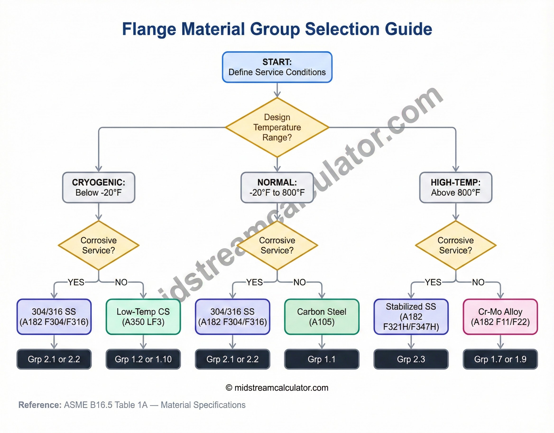
When to Use Higher Groups
- High temperature (>800°F): Cr-Mo alloys (Groups 1.7, 1.9) resist creep better than carbon steel
- Corrosive service: 304/316 stainless (Groups 2.1, 2.2) for acids, chlorides, sour gas
- Cryogenic (<-50°F): Austenitic stainless (Group 2.1+) retains toughness at low temps
- Marine/seawater: Monel or duplex stainless for pitting resistance
Cost trade-off: Stainless flanges cost 3–5× more than carbon steel but may allow a lower class at high temperatures, potentially offsetting material cost.
4. Flange Class Selection
Proper class selection ensures safe operation while avoiding over-specification that increases cost and weight.
Selection Steps
2. Select material group based on corrosion and temperature needs
3. Apply safety factor: Preq = Pd × 1.1 to 1.25
4. Look up P-T table for material group at Td
5. Select lowest class where rated pressure ≥ Preq
Selection Examples
| Application | Design Conditions | Class | Material |
|---|---|---|---|
| Water main | 150 psig, 80°F | 150 | A105 (rated 285 psig) |
| Gas gathering | 600 psig, 150°F | 600 | A105 (rated 1,430 psig) |
| Steam header | 400 psig, 600°F | 600 | A105 (rated 1,095 psig @ 600°F) |
| Sour gas | 900 psig, 200°F | 900 | F316 (corrosion + pressure) |
| High-temp process | 300 psig, 900°F | 600 | F22 Cr-Mo (rated 555 psig @ 900°F) |
| LNG cryogenic | 150 psig, -260°F | 300 | F304 SS (cryogenic toughness) |
Account for transients: Include margin for pressure surges, relief valve accumulation (10% overpressure), temperature excursions during upsets, and corrosion allowance.
5. Cyclic Service Derating
Repeated pressure or thermal cycling causes fatigue. ASME B31.3 defines "severe cyclic conditions" when stress exceeds 80% of allowable and cycles exceed 7,000. For such service, apply derating or enhanced construction.
Cyclic Service Classification
| Service Type | Cycle Count | Derating Factor | Notes |
|---|---|---|---|
| Normal | ≤ 1,000 | 1.00 | Standard design |
| Moderate Cyclic | 1,000 – 7,000 | 0.80 | Enhanced inspection recommended |
| Severe Cyclic | > 7,000 | 0.67 | Per B31.3 Para. 300.2 |
| High-Cycle Fatigue | > 100,000 | ≤ 0.50 | Use B31.3 Appendix W analysis |
Example: Class 600 at 400°F is rated 1,270 psig. For severe cyclic service (>7,000 cycles):
Pderated = 1,270 × 0.67 = 851 psig
Cycle sources: Daily startups/shutdowns, batch operations, pressure swings from compressors, thermal cycling from intermittent flow, and vibration from rotating equipment.
Fatigue Analysis per ASME B31.3 Appendix W
For detailed fatigue assessment in severe cyclic service:
Thermal Cycling Effects
Temperature cycles cause differential expansion and stress:
| ΔT Cycle Range | Thermal Stress Level | Design Action |
|---|---|---|
| < 100°F | Low | Standard design adequate |
| 100-200°F | Moderate | Consider expansion loops, flexibility analysis |
| 200-400°F | High | Detailed flexibility analysis required per ASME B31.3 |
| > 400°F | Severe | Spring supports, expansion joints, or special materials |
Enhanced Inspection for Cyclic Service
- Baseline inspection: Ultrasonic thickness measurements at installation
- Periodic inspection: Every 1-5 years depending on cycle count and stress level
- Focus areas: Flanges, welds, branch connections, areas of constraint
- Inspection methods: UT, liquid penetrant (PT), magnetic particle (MT), visual
- Acceptance criteria: Any crack indication = immediate evaluation/repair
6. Large Diameter Flanges (ASME B16.47)
For pipe sizes NPS 26 and larger, ASME B16.47 covers two series of flanges: Series A (comparable to API 605) and Series B (comparable to ASME B16.5 scaling).
B16.47 Series Comparison
| Feature | Series A | Series B |
|---|---|---|
| Size range | NPS 26 - 60 | NPS 26 - 60 |
| Bolt pattern | API 605 based | B16.5 extrapolation |
| Pressure classes | 75, 150, 300, 400, 600, 900 | 75, 150, 300, 400, 600, 900 |
| Weight | Lighter (fewer/smaller bolts) | Heavier (more/larger bolts) |
| Industry preference | Common in oil/gas pipelines | Less common, higher strength margin |
Class 300 Large Flange Ratings (Group 1.1)
| Size (NPS) | Bolts (Series A) | Bolts (Series B) | Bolt Size | Weight (lb) Series A |
|---|---|---|---|---|
| 26 | 28 × 1¼" | 32 × 1¼" | 1¼" | 750 |
| 30 | 28 × 1½" | 32 × 1½" | 1½" | 950 |
| 36 | 32 × 1½" | 40 × 1½" | 1½" | 1,250 |
| 42 | 36 × 1¾" | 44 × 1¾" | 1¾" | 1,850 |
| 48 | 44 × 1¾" | 52 × 1¾" | 1¾" | 2,450 |
| 60 | 52 × 2" | 60 × 2" | 2" | 3,800 |
Weights are approximate for weld neck flanges, carbon steel
Pressure-Temperature Ratings
B16.47 flanges use the same P-T tables as B16.5 for material groups. Temperature derating is identical.
Series compatibility: Series A and Series B flanges are NOT interchangeable—different bolt circles, hole sizes, and bolt counts. Always specify series when ordering large diameter flanges.
7. Valve Pressure Ratings (ASME B16.34)
ASME B16.34 specifies pressure-temperature ratings for valves. Valve ratings are coordinated with flange ratings to ensure compatible joints.
Valve Rating Consistency
Valves must be rated for the same or higher class as the connecting flanges:
Valve Body Material Groups
B16.34 uses same material groupings as B16.5:
| Group | Valve Body Material | ASTM Spec | Application |
|---|---|---|---|
| 1.1 | Carbon steel (cast) | A216 WCB | General service, -20°F to 1,000°F |
| 1.2 | Carbon steel (forged) | A105 | Small valves, threaded connections |
| 1.9 | 2¼Cr-1Mo | A217 WC9 | High temp service, up to 1,100°F |
| 2.1 | CF8 (304 cast SS) | A351 CF8 | Corrosion resistance, -425°F to 1,500°F |
| 2.2 | CF8M (316 cast SS) | A351 CF8M | Superior corrosion resistance |
Pressure Testing of Valves
Valves are hydrostatically tested before shipment per B16.34:
| Test Type | Test Pressure | Duration | Acceptance Criteria |
|---|---|---|---|
| Shell test | 1.5 × rated pressure at 100°F | Per B16.34 Table 8 | No visible leaks |
| Seat test (gate/globe) | 1.1 × rated pressure | Per manufacturer | No visible leaks |
| Seat test (check) | Per B16.34 Table 10 | Per manufacturer | Max leakage per API 598 |
| Seat test (ball) | 1.1 × rated pressure | Per manufacturer | Zero leakage (API 6D) |
Critical point: Valve pressure rating applies to body strength. Seat tightness is a separate specification covered by API 598 (general valves) and API 6D (pipeline valves). Seat leakage classifications range from Class I (most stringent, zero visible leakage) to Class VI (50 ml/hr per inch of seat diameter for soft-seated valves).
8. Gasket Selection for Flange Ratings
Gasket material must be compatible with flange rating, service temperature, and fluid. Incorrect gasket selection is a leading cause of flange joint leakage.
Gasket Types by Pressure Class
| Flange Class | Typical Gasket Type | Material | Temp Range |
|---|---|---|---|
| 150-300 | Full-face or ring | Compressed fiber, rubber, graphite | -100°F to 750°F |
| 400-600 | Spiral-wound with centering ring | Graphite filler, 316 SS winding | -325°F to 1,000°F |
| 900-1500 | Spiral-wound or metal | Graphite or corrugated metal | -450°F to 1,200°F |
| 2500 | Ring joint (RTJ) | Soft iron, 304 SS, Monel | -450°F to 1,000°F |
Gasket Factor (m) and Seating Stress (y)
ASME B16.5 Appendix S provides gasket factors for bolt load calculations:
| Gasket Type | m Factor | y (psi) | Service Limitation |
|---|---|---|---|
| Rubber, flat | 0.50 | 0 | Low pressure only |
| Compressed fiber | 1.25 | 1,600 | ≤ 400°F |
| Graphite (flexible) | 1.75 | 4,500 | Up to 750°F |
| Spiral-wound (graphite) | 3.00 | 10,000 | Up to 1,000°F |
| Metal (corrugated) | 3.75 | 14,500 | High temp/pressure |
| Ring joint (RTJ) | 5.50 | 18,000 | Highest ratings |
Bolt Load Calculation
Required bolt load to seat and maintain gasket seal:
Torque Requirements
Proper bolt torque is critical for gasket sealing:
| Bolt Size | Class 150 (ft-lb) | Class 300 (ft-lb) | Class 600 (ft-lb) | Class 900+ (ft-lb) |
|---|---|---|---|---|
| ½" | 15 | 20 | 25 | Hydraulic tensioning |
| ⅝" | 30 | 40 | 50 | Hydraulic tensioning |
| ¾" | 50 | 65 | 85 | Hydraulic tensioning |
| ⅞" | 75 | 100 | 130 | Hydraulic tensioning |
| 1" | 110 | 145 | 190 | Hydraulic tensioning |
| 1⅛" | 150 | 200 | 260 | Hydraulic tensioning |
| 1¼" | 200 | 265 | 350 | Hydraulic tensioning |
Values are approximate for lubricated B7 studs. Actual values depend on gasket type, material, and assembly procedure. For Class 900+, hydraulic tensioning strongly recommended.
Torque procedure: Use cross-pattern tightening (star pattern), three passes at 30%, 60%, and 100% of target torque. Never tighten bolts sequentially around the flange—this causes uneven gasket compression and potential leakage or flange warping.
9. Common Design and Selection Errors
Flange rating errors lead to leaks, failures, and safety incidents. Avoid these frequent mistakes:
Top 10 Flange Rating Errors
| Error | Consequence | Prevention |
|---|---|---|
| Using class number as pressure rating | Class 150 ≠ 150 psi! Leads to under-design | Always reference P-T tables for actual rating |
| Ignoring temperature derating | High-temp service exceeds rating, flange fails | Check rating at design temperature, not ambient |
| Mixing flange classes | Class 300 won't mate with Class 600 (different bolt patterns) | Verify all flanges in joint are same class |
| Wrong material group | Group 1.1 rating used for Group 2.1 material | Match material group to actual flange material spec |
| Inadequate gasket for service | Gasket blows out, leakage, fire/explosion risk | Select gasket rated for pressure, temp, and fluid |
| Forgetting surge pressure | Water hammer or valve closure exceeds rating | Add 10-25% margin for transients |
| B16.47 Series A/B mix | Bolt holes don't align, cannot assemble | Specify series explicitly on drawings |
| Insufficient bolt torque | Gasket not properly seated, leaks under pressure | Use torque wrench, follow tightening procedure |
| Excessive bolt torque | Gasket crushed, bolt yielding, flange warping | Don't exceed specified torque, use lubricant |
| Cyclic service not considered | Fatigue cracking in flanges or bolts | Apply derating factors for >7,000 cycles |
Real-World Failure Case Studies
Design Review Checklist
Verify these items before finalizing flange selection:
- ☐ Pressure rating at design temperature verified from P-T table
- ☐ Surge/transient pressure margin included (10-25%)
- ☐ Material group matches actual flange material specification
- ☐ Corrosion/environmental compatibility checked (sour, chloride, cryogenic)
- ☐ All flanges in joint are same class
- ☐ B16.47 series (A or B) specified if NPS ≥ 26
- ☐ Gasket type and material suitable for P, T, and fluid
- ☐ Bolt material specified (typically ASTM A193 B7 or B7M)
- ☐ Torque values calculated or specified
- ☐ Cyclic service evaluation if >1,000 cycles expected
- ☐ Low-temperature impact testing required? (ASME B31.3 Table A-1)
- ☐ Hydrotest pressure specified (typically 1.5× design pressure)
10. Bolt and Stud Material Selection
Flange bolts (studs + nuts) must be compatible with flange rating, temperature, and environment. ASTM A193/A194 specifications cover bolting materials.
Standard Bolt Materials by Service
| Service Condition | Stud Material (ASTM A193) | Nut Material (ASTM A194) | Temperature Range |
|---|---|---|---|
| General service | B7 (Cr-Mo steel) | 2H (carbon steel) | -20°F to 1,000°F |
| Low temperature | B7M (Cr-Mo, impact tested) | 2HM | -50°F to 1,000°F |
| Corrosive service | B8 (304 SS) | 8 (304 SS) | -325°F to 1,500°F |
| Sour/corrosive | B8M (316 SS) | 8M (316 SS) | -325°F to 1,500°F |
| High strength (Class 2500) | B16 (Cr-Mo-V) | 7 | -20°F to 1,100°F |
Allowable Bolt Stress by Temperature
Bolt stress decreases at elevated temperature, similar to flange derating:
| Temperature (°F) | A193 B7 (ksi) | A193 B8 (ksi) | A193 B8M (ksi) |
|---|---|---|---|
| -20 to 100 | 25.0 | 20.0 | 20.0 |
| 200 | 25.0 | 18.3 | 18.3 |
| 400 | 25.0 | 15.8 | 16.7 |
| 600 | 23.3 | 13.8 | 14.6 |
| 800 | 17.5 | 11.7 | 12.9 |
| 1,000 | 10.0 | 9.5 | 11.3 |
Bolt Lubrication
Proper lubrication critical for achieving correct preload:
- Never-seize compound: Most common, nickel or copper-based, prevents galling
- Teflon tape on threads: Allowed for gas service, easier disassembly
- Graphite-based: High-temperature service (>800°F)
- Molybdenum disulfide (moly): High-load applications
Torque vs. tension: Torque is a poor proxy for bolt tension (actual clamping force). 80% of applied torque overcomes friction; only 20% creates tension. For critical joints (Class 900+), use hydraulic tensioners that directly measure and apply bolt load.
Cold Weather Bolting Precautions
Bolting below -20°F requires special considerations:
- Impact testing: Use B7M (not B7) for temperatures below -50°F
- Warm bolts before tightening: Heat to 50-70°F to reduce brittleness
- Reduced torque rate: Tighten slower to avoid sudden loading
- Re-torque after warmup: Thermal expansion may loosen bolts after system warms
Reference Standards
| ASME B16.5 | Pipe Flanges and Flanged Fittings (NPS ½ – 24) |
| ASME B16.47 | Large Diameter Steel Flanges (NPS 26 – 60) |
| ASME B16.34 | Valves—Flanged, Threaded, and Welding End |
| ASME B31.3 | Process Piping (design and cyclic service requirements) |
| ASME B31.8 | Gas Transmission and Distribution Piping Systems |
| ASME Sec II-D | Material Properties and Allowable Stresses |
| ASTM A193/A194 | Alloy-Steel and Stainless Steel Bolting Materials |
| API 598 | Valve Inspection and Testing |
| API 6D | Pipeline Valves (specification and testing) |
| NACE MR0175/ISO 15156 | Petroleum and Natural Gas Industries—Materials for Use in H₂S Environments |
Ready to use the calculator?
→ Launch Calculator