1. Volume Calculation
Pipe internal volume is calculated from the inside diameter and length. Various unit conversions are needed for practical applications.
Basic Formulas
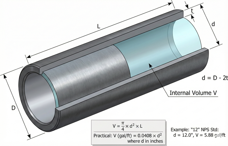
Inside Diameter
Unit Conversions
| From | To | Multiply by | Source |
|---|---|---|---|
| ft³ | US gallons | 7.480519 | API MPMS |
| ft³ | barrels (42 gal) | 0.178108 | API |
| gallons | barrels | 0.023810 | API |
| ft³ | liters | 28.31685 | NIST |
| gallons | liters | 3.785412 | NIST |
| barrels | liters | 158.987 | API |
2. Volume Reference Tables
Standard Pipe Volumes
| NPS | OD (in) | Wall (Std) | ID (in) | gal/ft | bbl/mile |
|---|---|---|---|---|---|
| 2" | 2.375 | 0.154 | 2.067 | 0.174 | 21.9 |
| 4" | 4.500 | 0.237 | 4.026 | 0.661 | 83.4 |
| 6" | 6.625 | 0.280 | 6.065 | 1.501 | 189.4 |
| 8" | 8.625 | 0.322 | 7.981 | 2.599 | 327.9 |
| 10" | 10.750 | 0.365 | 10.020 | 4.098 | 517.0 |
| 12" | 12.750 | 0.375 | 12.000 | 5.875 | 741.2 |
| 16" | 16.000 | 0.375 | 15.250 | 9.489 | 1,197 |
| 20" | 20.000 | 0.375 | 19.250 | 15.12 | 1,907 |
| 24" | 24.000 | 0.375 | 23.250 | 22.05 | 2,782 |
| 30" | 30.000 | 0.375 | 29.250 | 34.90 | 4,403 |
| 36" | 36.000 | 0.375 | 35.250 | 50.71 | 6,398 |
| 42" | 42.000 | 0.500 | 41.000 | 68.60 | 8,655 |
Quick Reference: Volume per Mile
3. Gas Volume at Pressure
For gas pipelines, volume must account for compressibility. The actual gas quantity depends on pressure, temperature, and gas composition.
Gas Inventory Calculation
Z-Factor Estimation
The compressibility factor Z accounts for real gas behavior. For natural gas:
Line Pack Formula
Example: Gas Pipeline Inventory
Given: 24" × 0.500" wall, 100 miles, P_avg = 800 psia, T = 70°F, SG = 0.60
Step 1: Physical volume
ID = 24 - 2(0.500) = 23 in
V = 0.00545 × 23² × 5,280 × 100 = 15.23 MM ft³
Step 2: Z-factor (from DAK correlation)
T_pc = 169.2 + 349.5(0.60) - 74.0(0.36) = 352.5°R
P_pc = 756.8 - 131.0(0.60) - 3.6(0.36) = 676.8 psia
T_pr = 530/352.5 = 1.50; P_pr = 800/676.8 = 1.18
Z ≈ 0.87
Step 3: Line pack
SCF = 15.23×10⁶ × 800 × 35.34 / (530 × 0.87)
SCF = 934 MMSCF
4. Applications
Common Uses
| Application | Purpose |
|---|---|
| Hydrotesting | Calculate water volume needed for test |
| Purging/inerting | Determine nitrogen volume for displacement |
| Pigging | Estimate pig travel time at given flow rate |
| Batch tracking | Calculate batch interface location |
| Line pack | Gas storage capacity in pipeline |
| Blowdown | Gas release volume for depressuring |
| Chemical treatment | Inhibitor/biocide dosing volume |
Hydrotest Water Requirements
Pig Travel Time
5. System Volume
Total system volume includes pipe plus vessels, headers, and fittings.
Vessel Volumes
Fitting Equivalent Volumes
| Fitting | Equivalent Pipe Length |
|---|---|
| 90° elbow (LR) | 1.5 × D |
| 90° elbow (SR) | 1.0 × D |
| 45° elbow | 0.7 × D |
| Tee (through) | 1.0 × D |
| Tee (branch) | 1.5 × D |
| Gate valve (open) | 0.5 × D |
| Ball valve (open) | 0.1 × D |
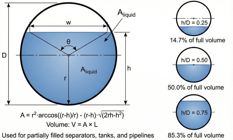
Partially Filled Horizontal Pipe
References
- ASME B36.10M – Welded and Seamless Wrought Steel Pipe
- API MPMS Chapter 11.1 – Temperature and Pressure Volume Correction
- AGA Report No. 8 – Compressibility and Supercompressibility Factors
- GPSA, Section 17 – Fluid Properties
- Dranchuk & Abou-Kassem (1975) – Z-Factor Calculation Methods
- Sutton (1985) – Pseudo-Critical Property Correlations
Ready to use the calculator?
→ Launch Calculator