Gas Processing

Gas Separation Membrane Technology

Design membrane separation systems for CO2 removal, N2 rejection, and hydrocarbon recovery using permeability and selectivity principles, multi-stage configurations with recycle, and economic analysis vs. amine treating and cryogenic processing.

Permeability

Fast gas permeates first

CO2 and H2O permeate ~50× faster than CH4 through polymer membranes.

Selectivity

α = P_A / P_B

CO2/CH4 selectivity of 20-50 for cellulose acetate membranes.

Operating pressure

800-1200 psig feed

Higher feed pressure increases driving force and membrane throughput.

Use this guide when you need to:

  • Design membrane systems for acid gas removal.
  • Calculate permeate and residue compositions.
  • Optimize multi-stage configurations with recycle.
  • Compare membrane economics to amine or cryogenic.

1. Overview & Applications

Gas separation membranes use selective permeation to separate components based on differences in permeability through a thin polymer film. They offer modular, low-maintenance alternatives to amine absorption and cryogenic processes.

Cross-sectional cutaway of hollow fiber membrane module showing feed gas entering shell side at 1000 psig, hollow fiber bundle, tube sheet, permeate exiting fiber lumens at 50 psig, and retentate (sales gas) exiting opposite end, with inset detail of single fiber showing selective skin layer
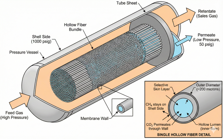
Hollow fiber membrane module: feed gas enters shell side at high pressure, CO₂ permeates through fiber walls to low-pressure lumens, CH₄-rich retentate exits as sales gas.

CO₂ removal

Acid gas treating

Remove CO₂ to meet pipeline spec (< 2-3% CO₂).

N₂ rejection

Heating value upgrade

Reduce N₂ to increase Btu content.

H₂ recovery

Refinery applications

Recover hydrogen from purge streams.

Dehydration

Water removal

Remove water vapor (H₂O permeates very fast).

Key Terms

Term Definition Typical Values
Permeability (P) Rate gas diffuses through membrane per unit ΔP 1-100 Barrer (CO₂)
Selectivity (α) Ratio of permeabilities: α = P_A / P_B 15-50 (CO₂/CH₄)
Stage cut (θ) Permeate flow / feed flow 0.15-0.30
Pressure ratio P_feed / P_permeate (higher is better) 10-20:1

Advantages vs. Disadvantages

Advantages Disadvantages
Low capital cost (modular, skid-mounted) Membrane replacement every 5-10 years
Low operating cost (no reboiler/refrigeration) Permeate at low pressure (may need recompression)
Minimal maintenance (no moving parts) Sensitive to liquids and contaminants
Compact footprint (offshore/remote) Difficult to achieve >98% purity
When to use membranes: Best for remote/offshore sites with 5-20% CO₂, high feed pressure (>600 psig), and moderate purity needs (2-3% CO₂ spec). Capital cost 30-50% lower than amine for these applications.

2. Permeability & Selectivity Fundamentals

Membrane separation is driven by partial pressure difference across the membrane. Performance depends on permeability (flux rate) and selectivity (separation factor).

Three-panel diagram showing solution-diffusion mechanism: Step 1 Sorption where gas dissolves into polymer at high pressure, Step 2 Diffusion where CO₂ moves 30x faster than CH₄ through polymer matrix, Step 3 Desorption where gas exits at low pressure. Formula P=S×D shown with permeation order
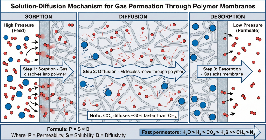
Solution-diffusion mechanism: gas molecules dissolve into membrane (sorption), diffuse through polymer matrix, and exit (desorption). CO₂ diffuses ~30× faster than CH₄.

Flux Equation

Permeate Flux: J_i = (P_i / t) × (p_feed,i - p_perm,i) Where: • J_i = Flux of component i (cm³(STP)/cm²·s) • P_i = Permeability (Barrer) • t = Membrane thickness (typically 0.1-1.0 μm) • Δp = Partial pressure driving force (psia) Units: 1 Barrer = 10⁻¹⁰ cm³(STP)·cm / (cm²·s·cmHg) 1 GPU = 10⁻⁶ cm³(STP) / (cm²·s·cmHg)

Gas Permeability Order

Gas Permeability (Barrer) Relative to CH₄ Behavior
H₂O 50,000-100,000 ~5000× Very fast (dehydration)
H₂ 200-500 ~100× Fast (H₂ recovery)
CO₂ 50-150 ~30× Fast (acid gas removal)
H₂S 60-200 ~40× Fast (acid gas removal)
CH₄ 2-5 1× (reference) Slow (retained in retentate)
N₂ 0.5-1.5 ~0.4× Very slow (N₂ rejection difficult)

Selectivity

Ideal Selectivity: α_A/B = P_A / P_B Examples: • CO₂/CH₄: α = 50/2.5 = 20 (cellulose acetate) • H₂S/CH₄: α = 80/2.5 = 32 • N₂/CH₄: α = 1.0/2.5 = 0.4 (N₂ slower than CH₄!) Note: Actual separation is 50-80% of ideal due to concentration polarization and pressure ratio effects.

Membrane Materials Comparison

Type α (CO₂/CH₄) Max Temp Application
Cellulose Acetate 15-30 140°F Most common, CO₂ removal
Polyimide 20-35 200°F High-temp applications
Polysulfone 10-27 180°F General purpose, durable
PDMS (Silicone) 3-5 250°F High flux, low selectivity

Operating Condition Effects

Temperature: • Higher T → Higher flux (Arrhenius: P doubles per 30-50°F) • Higher T → Lower selectivity • Optimum: 80-120°F for polymer membranes Pressure: • Higher feed pressure → Higher driving force → Higher flux • Increasing P_feed from 800 to 1200 psig reduces area ~33% • Target pressure ratio (P_feed/P_perm) > 10:1 for best separation
Critical insight: N₂/CH₄ selectivity <1 means standard membranes cannot reject N₂ from methane directly. For N₂ rejection, CH₄ must permeate (goes to low pressure), requiring recycle or special reverse-selective membranes.

3. CO₂ and N₂ Removal Applications

Membranes are used for CO₂ removal (acid gas treating) and N₂ rejection to meet pipeline specifications.

Process flow diagram for single-stage membrane CO₂ removal: feed gas 100 MMscfd at 10% CO₂ through filter/coalescer and feed heater to membrane skid, producing 93 MMscfd sales gas at 2% CO₂ and 7 MMscfd permeate at 80% CO₂. Material balance box and performance metrics shown
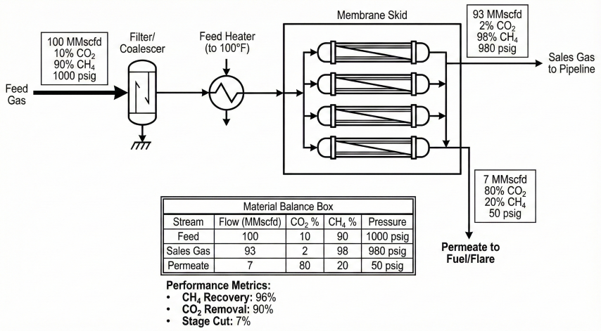
Single-stage membrane system for CO₂ removal: 96% CH₄ recovery, 90% CO₂ removal, 7% stage cut.

CO₂ Removal Design Example

Single-Stage (100 MMscfd, 15% CO₂ → <2% CO₂): Material Balance: • Feed: 100 MMscfd, 15% CO₂, 85% CH₄ • Retentate: ~93 MMscfd, 2% CO₂, 98% CH₄ (Sales Gas) • Permeate: ~7 MMscfd, ~80% CO₂ (Acid Gas) Stage cut θ ≈ 0.07 CH₄ Recovery ≈ 96% CO₂ Removal ≈ 90% Membrane Area: A = Q_perm / (J × ΔP_lm) Typical: 80,000-120,000 ft² for 100 MMscfd

CO₂ Removal Performance Guide

Feed CO₂ Target CH₄ Recovery Configuration
5-10% <2% 97-99% Single stage
10-20% <2% 95-97% Single or two-stage
20-40% <2% 92-95% Two-stage with recycle
>40% <2% 88-92% Consider amine instead

N₂ Rejection Challenge

Key Problem: N₂ permeates SLOWER than CH₄ (α = 0.4) Configuration is REVERSED from CO₂ removal: • CH₄ goes to permeate (low pressure) → Sales gas • N₂ concentrates in retentate (high pressure) → Reject stream Example: Feed: 100 MMscfd, 15% N₂ @ 1000 psig Permeate: 90 MMscfd, 4% N₂ @ 150 psig (Sales) Retentate: 10 MMscfd, 85% N₂ (Reject) Problem: Must recompress permeate to sales pressure → Economics depend on compression costs → Cryogenic often preferred for >30% N₂

Application Selection

Application Membrane? Alternative
CO₂ 5-20%, >600 psig Excellent Amine (higher purity)
CO₂ >40% Fair Amine preferred
N₂ <20%, >800 psig Good Cryogenic (purer)
Dehydration Excellent Glycol (lower dewpoint)
H₂ recovery Excellent PSA (higher purity)

Permeate Disposal Options

  • Fuel gas: Use permeate for on-site compressor/heater fuel
  • Flare: Only if permeate <5% of feed (CH₄ loss)
  • Recompression: Recover CH₄ if permeate >30% methane
  • EOR/Sequestration: High-purity CO₂ (>90%) for injection

4. Multi-Stage Design & Recycle

Single-stage sacrifices either purity or recovery. Multi-stage with recycle optimizes both.

Two-stage membrane system PFD with recycle: fresh feed 100 MMscfd at 20% CO₂ mixed with 10 MMscfd recycle, Stage 1 produces 94 MMscfd sales gas at 2% CO₂, permeate to Stage 2 produces acid gas at 90% CO₂, retentate recycled via compressor. Stream data table and performance metrics shown
Two-stage membrane with recycle: 97% CH₄ recovery (vs 92% single-stage), 10% recycle ratio, requires recycle compressor.

Two-Stage Configuration

Two-Stage Series with Recycle: Feed → [Stage 1] → Sales Gas (Retentate 1) ↓ Permeate 1 → [Stage 2] → Acid Gas (Permeate 2) ↓ Retentate 2 → Recycle to Feed Material Balance Example: Fresh feed: 100 MMscfd, 20% CO₂ Recycle: 10 MMscfd @ 12% CO₂ (ψ = 0.10) Stage 1 feed: 110 MMscfd Sales gas: 94 MMscfd, 2% CO₂ Acid gas: 6 MMscfd, 90% CO₂ CH₄ Recovery: 97% (vs. 92% single-stage)

Configuration Comparison

Configuration CH₄ Recovery Area (Relative) Complexity
Single stage 90-94% 1.0× Simple
Two-stage series 95-97% 1.3-1.5× Moderate
Two-stage parallel 96-98% 1.4-1.6× Moderate
Three-stage 97-99% 1.6-2.0× High

Design Rules of Thumb

Stage Cut Guidelines: • Stage 1: θ₁ = 0.10-0.20 (determines sales gas purity) • Stage 2: θ₂ = 0.40-0.60 (recover CH₄ from permeate) Recycle Ratio: • ψ = 0.05-0.20 (recycle 5-20% of fresh feed) • Higher ψ → Better recovery, larger Stage 1 Compressor Sizing: • Recycle: ~100-300 HP per 10 MMscfd (100→1000 psig)
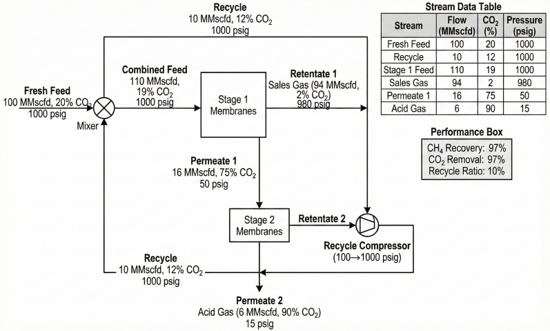
Recycle trade-off: Two-stage improves CH₄ recovery from 92% to 97%, but increases membrane area 30-50% and requires recycle compression. Optimize ψ based on CH₄ value vs. compression cost.

5. Economic Comparison

The choice between membrane, amine, and cryogenic depends on feed conditions, purity requirements, and site constraints.

Decision tree flowchart for gas treating technology selection: CO₂ removal branches to Membrane (5-25%, >600 psig) or Amine (>25% or <0.5% spec), N₂ rejection branches to Membrane (<15%, <20 MMscfd) or Cryogenic NRU (>30% or >20 MMscfd). Color-coded with cost ranges and decision factors comparison table
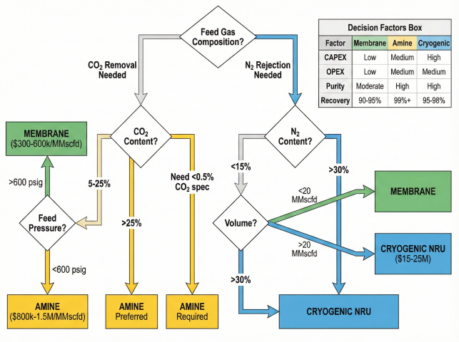
Technology selection decision tree: membrane preferred for moderate CO₂ (5-25%) at high pressure; amine for high CO₂ or stringent specs; cryogenic for N₂ rejection.

Capital Cost Comparison

Technology CAPEX ($/MMscfd) Installation
Membrane (single) $300k-600k 3-6 months
Membrane (two-stage) $500k-900k 6-9 months
Amine treating $800k-1.5M 12-18 months
Cryogenic NRU $3M-6M 24-30 months

Operating Cost Summary

Membrane (100 MMscfd, two-stage): • Membrane replacement: $700k-1.4M/yr (5-10 yr life) • Compression: ~$100k/yr • Maintenance: ~$50k/yr Total: ~$850k-1.5M/yr Amine (100 MMscfd): • Reboiler fuel: ~$800k/yr • Chemicals: ~$75k/yr • Labor: ~$200k/yr Total: ~$1.2M/yr Cryogenic: • Power/utilities: ~$750k/yr • Maintenance: ~$300k/yr • Labor: ~$300k/yr Total: ~$1.3-1.5M/yr

Selection Guide

Favor Membrane Favor Amine Favor Cryogenic
CO₂: 5-25% CO₂: >25% N₂ rejection
Spec: 2-3% CO₂ OK Spec: <50 ppm CO₂ NGL recovery needed
P_feed: >600 psig Any pressure P_feed: >800 psig
Remote/offshore Manned onshore Large onshore plant
Fast schedule (3-6 mo) 12-18 months OK 24+ months OK

Hybrid Systems

Membrane + Amine (High CO₂, stringent spec): • Membrane: 50% → 5-8% CO₂ (bulk removal) • Amine: 5% → <0.5% CO₂ (polishing) • Result: 85-90% smaller amine unit Cryogenic + Membrane (N₂ + NGL): • Cryogenic: NGL recovery first • Membrane: N₂ rejection on residue • Result: Better economics than cryogenic NRU alone
Membrane sweet spot: Remote/offshore with 5-20% CO₂, >800 psig feed, 2-3% CO₂ spec acceptable. For large plants, high CO₂ (>40%), or very low specs (<0.5%), amine is usually preferred.