Select appropriate carbon steel grades per API 5L, evaluate sour service requirements per ISO 15156 (NACE MR0175), determine temperature limits and impact testing needs per ASME B31.8, and specify corrosion allowance and coating systems.
Material selection for pipelines and piping systems must account for mechanical strength, corrosion resistance, operating temperature, fluid composition (especially H2S and CO2), and fabrication requirements.
Mechanical strength
SMYS and toughness
Select grade based on required wall thickness (SMYS) and fracture toughness.
Corrosion resistance
H2S, CO2, chlorides
Sour service (H2S) and sweet service (CO2) require specific material limits.
Temperature limits
-50°F to 250°F typical
Carbon steel service temperature range; impact testing below 32°F.
SMYS (Specified Minimum Yield Strength): Minimum yield strength in psi or MPa (e.g., X52 = 52,000 psi SMYS)
Sour service: Service containing H2S; requires materials resistant to sulfide stress cracking (SSC) and hydrogen-induced cracking (HIC)
Sweet service: Service containing CO2 but no H2S; CO2 corrosion managed by inhibitors, coatings, or corrosion allowance
Impact testing: Charpy V-notch (CVN) testing to verify toughness at minimum design temperature
Corrosion allowance (CA): Extra wall thickness beyond pressure design to accommodate metal loss over service life
Why material selection matters: Incorrect material selection can lead to catastrophic failures. Using non-sour-rated material in H2S service causes sulfide stress cracking. Inadequate toughness at low temperature leads to brittle fracture. Insufficient corrosion allowance results in leaks and failures before design life.
2. Carbon Steel Grades
Carbon steel is the most common material for oil and gas pipelines and piping due to low cost, availability, and adequate strength. API 5L and ASTM standards specify composition, mechanical properties, and testing requirements.
API 5L Pipeline Grades
Grade
SMYS (psi)
SMYS (MPa)
Tensile (psi)
Typical Application
API 5L Grade B
35,000
241
60,000
Low pressure gathering, older pipelines
API 5L X42
42,000
290
60,000
Gathering systems, distribution
API 5L X52
52,000
359
66,000
Transmission, most common grade
API 5L X60
60,000
414
75,000
High-pressure transmission
API 5L X65
65,000
448
77,000
High-pressure transmission, offshore
API 5L X70
70,000
483
82,000
High-pressure transmission, Arctic
API 5L X80
80,000
552
90,000
Ultra-high pressure, specialized applications
API 5L PSL 1 vs. PSL 2
Product Specification Levels:
PSL 1 (Product Specification Level 1):
- Standard quality
- Limited chemical composition requirements
- No mandatory impact testing
- Lower cost
- Suitable for non-critical applications
PSL 2 (Product Specification Level 2):
- Higher quality and tighter tolerances
- Stricter chemical composition (C, Mn, P, S, Cu, Ni, Cr, Mo, V limits)
- Mandatory Charpy V-notch testing at specified temperature
- Non-destructive examination (NDE) requirements
- Supplementary requirements available (sour service SR15, HIC SR17)
- Required for sour service, offshore, Arctic, high-consequence areas
Chemical Composition Limits (PSL 2, X52 example):
C: ≤ 0.26%
Mn: ≤ 1.40%
P: ≤ 0.025%
S: ≤ 0.015%
C_eq: ≤ 0.43% (weldability limit)
Where:
C_eq = C + Mn/6 + (Cr+Mo+V)/5 + (Ni+Cu)/15
ASTM Pipe and Tube Grades
Specification
Type/Grade
SMYS (psi)
Application
ASTM A106
Grade B
35,000
Seamless pipe for high-temp service (to 750°F)
ASTM A53
Grade B
35,000
Welded or seamless pipe, general purpose
ASTM A333
Grade 6
35,000
Low-temp service (to -50°F), impact tested
ASTM A694
F52, F60, F65
52,000-65,000
Forgings for flanges, fittings (high strength)
ASTM A105
—
36,000
Carbon steel forgings for flanges, valves (ambient to 650°F)
Grade Selection Based on Design Pressure
Barlow's Formula (ASME B31.8):
t = (P × D) / (2 × S × E × F × T)
Where:
t = Minimum wall thickness (in)
P = Design pressure (psig)
D = Outside diameter (in)
S = SMYS (psi)
E = Longitudinal joint factor (1.0 seamless, 1.0 ERW, 0.80 furnace butt weld)
F = Design factor (0.72 typical Class 1, 0.60 Class 2, 0.50 Class 3)
T = Temperature derating factor (1.0 for T ≤ 250°F)
Example:
Design 24" OD pipeline for 1440 psig, Class 1 location (F=0.72).
Using X52 (SMYS = 52,000 psi):
t = (1440 × 24) / (2 × 52,000 × 1.0 × 0.72 × 1.0)
t = 34,560 / 74,880 = 0.461 in
Select: 0.500 in wall (standard size)
Using X65 (SMYS = 65,000 psi):
t = (1440 × 24) / (2 × 65,000 × 0.72)
t = 34,560 / 93,600 = 0.369 in
Select: 0.375 in wall (thinner, lighter, less expensive)
Higher grade → thinner wall for same pressure
Trade-off: Material cost vs. weight/installation cost
Weldability and Heat Treatment
Grade
C_eq Typical
Preheat Required
PWHT Required
Weldability
X42-X52
0.38-0.43
Not usually (if T > 32°F)
No (unless t > 1.25 in)
Excellent
X60-X65
0.43-0.47
Yes, 200-300°F
Optional (sour service: yes)
Good
X70-X80
0.45-0.50
Yes, 250-400°F
Yes (especially sour service)
Fair (requires controlled procedures)
Grade selection trade-offs: Higher strength grades (X70, X80) reduce wall thickness and weight, lowering installation costs for large-diameter pipelines. However, they require stricter welding procedures, higher material cost, and may have reduced toughness at low temperature. For most applications, X52 or X60 provides best balance of cost, weldability, and performance.
3. Sour Service Requirements
Sour service (presence of H2S) requires materials resistant to sulfide stress cracking (SSC), hydrogen-induced cracking (HIC), and stress-oriented hydrogen-induced cracking (SOHIC). NACE MR0175 / ISO 15156 defines material limits.
Sour Service Definition
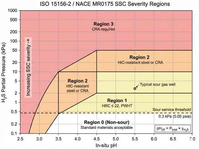
ISO 15156 / NACE MR0175 Sour Service Criteria:
Sour service exists when BOTH conditions are met:
1. H₂S partial pressure > 0.05 psia (0.3 kPa)
P_H2S = P_total × y_H2S
Where:
P_total = Total pressure (psia)
y_H2S = Mole fraction of H₂S in gas phase
2. Water (aqueous phase) is present
If no water → not sour service (dry H₂S is not corrosive)
Example:
Gas at 1000 psia contains 100 ppm H₂S (0.0001 mole fraction).
P_H2S = 1000 × 0.0001 = 0.1 psia
0.1 > 0.05 → SOUR SERVICE if water is present ✓
Even 50 ppm H₂S at 1000 psia (pH₂S = 0.05 psia) triggers sour service.
ISO 15156-2 SSC severity regions for sour service material selection.
ISO 15156-2 SSC Regions
Region
Severity
pH₂S Range
Material Requirements
Region 0
Non-sour
< 0.3 kPa (0.05 psia)
No SSC requirements; standard materials acceptable
Region 1
Low
0.3-1 kPa at pH ≥ 4.5
Carbon steel with HRC ≤ 22, PWHT required
Region 2
Moderate
1-10 kPa at pH ≥ 4.5
HIC-resistant steel (SR17) or CRA required
Region 3
Severe
> 10 kPa or low pH
CRA required; full ISO 15156 qualification
SSC Resistance Requirements
Hardness Limits (NACE MR0175-3):
Carbon steel (weld metal, HAZ, base metal):
- Maximum hardness: 22 HRC (248 HV, 237 HB)
- Applies to ALL regions: base metal, weld, HAZ
If hardness > 22 HRC → susceptible to SSC → NOT ACCEPTABLE
Hardness Testing:
Method: Rockwell C (HRC), Vickers (HV), or Brinell (HB)
Spacing: Every 2 in along weld and HAZ
Acceptance: 100% of readings ≤ 22 HRC
Conversion (approximate):
22 HRC = 248 HV = 237 HB
Achieving HRC ≤ 22:
- Limit carbon equivalent: C_eq ≤ 0.43%
- Post-weld heat treatment (PWHT): 1100-1200°F for 1 hr/in thickness
- Controlled cooling rate after welding
- Low-hydrogen welding electrodes (E7018, E8018)
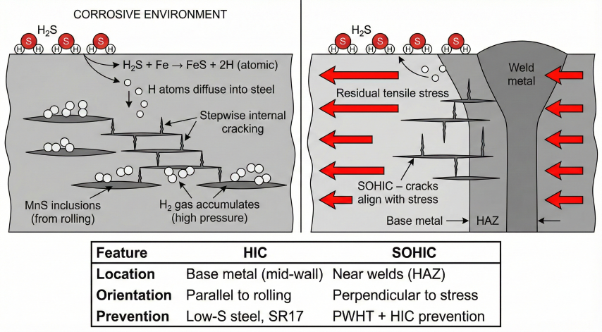
HIC and SOHIC Resistance
HIC and SOHIC cracking mechanisms in carbon steel exposed to H₂S service.
Hydrogen-Induced Cracking (HIC):
Occurs in base metal due to atomic hydrogen from H₂S corrosion.
Hydrogen accumulates at inclusions/laminations → internal cracks.
Prevention:
- Use HIC-resistant steel (low sulfur ≤0.002%, Ca-treated, controlled rolling)
- API 5L PSL 2 Supplementary Requirement SR17 (HIC testing)
HIC testing per NACE TM0284:
- 96-hour immersion in synthetic sour brine (H₂S saturated, pH 2.7)
- Ultrasonic inspection for cracks
- Acceptance: CLR < 15%, CTR < 5%, CSR < 2%
Where:
CLR = Crack Length Ratio (Σcrack lengths / specimen width)
CTR = Crack Thickness Ratio (Σcrack heights / specimen thickness)
CSR = Crack Sensitivity Ratio (Σcrack areas / specimen cross-section)
Stress-Oriented HIC (SOHIC):
HIC + tensile stress (especially in heat-affected zone).
Occurs near welds in high-stress regions.
Prevention:
- Same as HIC prevention
- PWHT to reduce residual stress (1100-1200°F for 1 hr/in)
- Avoid stress concentrations (smooth transitions, generous radii)
Sour Service Material Selection
Material
Specification
SSC Resistant?
HIC Resistant?
Comments
API 5L PSL 2 X42-X65
With SR15 (SSC)
Yes (if HRC ≤ 22)
No (unless SR17)
PWHT required to meet hardness; verify by testing
API 5L PSL 2 + SR17
HIC tested
Yes
Yes
Preferred for sour service; higher cost
ASTM A106 Grade B
PWHT required
Yes (with PWHT)
No
Piping; PWHT to reduce hardness
13Cr stainless
Modified (≤ 0.01% C)
Yes
Yes
Used for severe sour + CO2; expensive
Duplex stainless (22Cr)
UNS S31803
Yes
Yes
Excellent sour + chloride resistance; very expensive
Inconel 625, 825
Nickel alloys
Yes
Yes
Extreme sour service; highest cost
PWHT Requirements for Sour Service
Post-Weld Heat Treatment (PWHT):
Purpose:
- Reduce hardness in HAZ and weld metal
- Relieve residual stresses
- Improve toughness
Temperature: 1100-1250°F (593-677°C)
Holding time: 1 hour per inch of thickness (minimum 30 min)
Heating/cooling rate: < 400°F/hr (< 220°C/hr)
When PWHT is Required:
ALWAYS for sour service if:
- Wall thickness > 0.75 in (19 mm)
- Grade X60 or higher
- P_H2S > 3 psia
- Design temperature < 32°F
OPTIONAL for sour service if:
- Wall thickness < 0.75 in
- Grade X52 or lower
- Hardness testing confirms HRC ≤ 22 without PWHT
Exemptions:
- Small-bore piping (≤ 2 in NPS, ≤ 0.5 in thick)
- Stub-in connections with fillet welds
- If hardness survey proves HRC ≤ 22 without PWHT
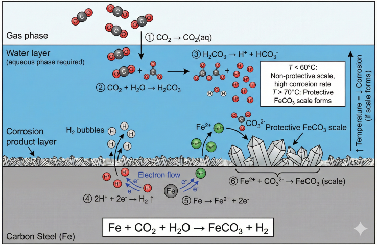
Sweet Service (CO₂ Only)
CO₂ corrosion mechanism showing electrochemical reactions and protective scale formation.
CO₂ Corrosion (No H₂S):
CO₂ + H₂O → H₂CO₃ (carbonic acid) → general/localized corrosion
Corrosion rate depends on:
- CO₂ partial pressure (P_CO2)
- Temperature (max rate ~70-80°C)
- Flow velocity (wall shear stress)
- In-situ pH, water chemistry
de Waard-Milliams Correlation (screening):
log(CR) = 5.8 - 1710/T + 0.67×log(pCO₂)
Where: CR = mm/yr, T = Kelvin, pCO₂ = bar
pCO₂ < 0.5 bar (7 psia): Low risk (<5 mpy)
0.5 < pCO₂ < 2 bar (7-30 psia): Moderate risk (5-20 mpy)
pCO₂ > 2 bar (30 psia): High risk (>20 mpy)
Mitigation Options:
- Corrosion inhibitor injection (85-95% efficiency)
- Internal coating (epoxy, FBE, phenolic)
- Corrosion allowance (3-6 mm typical)
- pH stabilization (raise pH to form protective FeCO₃ scale)
- CRA upgrade (13Cr, Duplex for severe cases)
Sweet service does NOT require HRC ≤ 22 or PWHT (unless other factors).
Standard carbon steel (API 5L PSL 1 or PSL 2) is acceptable.
Sour service cost impact: Sour service materials (PSL 2 with SR15/SR17) cost 15-30% more than standard pipe. PWHT adds $5-20 per inch-diameter-foot for field welds. Hardness testing adds inspection time and cost. For marginal sour service (P_H2S near 0.05 psia), consider operating changes (dehydration, H2S scavenging) to eliminate sour service requirements and reduce costs.
4. Temperature Limits & Impact Testing
Carbon steel service temperature is limited by creep (high temperature) and brittle fracture (low temperature). Impact testing verifies adequate toughness at minimum design temperature.
Carbon Steel Temperature Limits
Temperature Range
Material Behavior
Requirements
-50°F to -20°F
Potential brittle fracture
Impact testing mandatory; ASTM A333 or normalized steel
-20°F to 32°F
Ductile-to-brittle transition
Impact testing required per ASME B31.8 Table 841.1.8-1
32°F to 250°F
Normal ductile behavior
No special requirements; standard carbon steel
250°F to 650°F
Strength reduction, no creep
Temperature derating factor (T < 1.0); use ASTM A106
> 650°F
Creep, oxidation
Alloy steel (Cr-Mo); carbon steel not recommended
Impact Testing Requirements (ASME B31.8)
When Impact Testing is Required:
Per ASME B31.8 Table 841.1.8-1:
Impact testing is REQUIRED if:
1. Design temperature < 32°F (0°C), OR
2. Design temperature < 50°F (10°C) AND wall thickness > 0.75 in, OR
3. Specified by pipeline specifications (e.g., Arctic, offshore)
Impact testing is EXEMPT if:
- Temperature ≥ 50°F and t ≤ 0.75 in
- Material is normalized (heat treated for improved toughness)
- Material specification includes mandatory impact testing (API 5L PSL 2)
Charpy V-Notch (CVN) Requirements:
Test temperature: Minimum design temperature or -20°F, whichever is LOWER
Acceptance criteria (ASME B31.8):
- Average of 3 specimens: ≥ 15 ft·lb (20 J)
- Minimum single specimen: ≥ 12 ft·lb (16 J)
Higher toughness preferred:
- Onshore transmission: 20-30 ft·lb average
- Offshore, Arctic: 40-60 ft·lb average
- HCA (High Consequence Area): 30+ ft·lb average
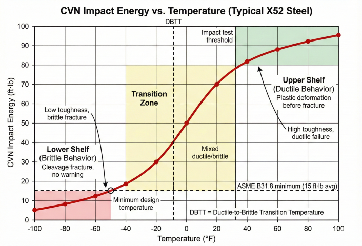
Brittle Fracture Mechanism
Ductile-to-brittle transition curve showing CVN impact energy vs. temperature for carbon steel.
Ductile-to-Brittle Transition:
At low temperature, carbon steel transitions from ductile (plastic deformation)
to brittle (cleavage fracture) behavior.
Transition temperature depends on:
- Carbon content (higher C → higher DBTT)
- Grain size (finer grain → lower DBTT)
- Alloy content (Ni lowers DBTT; P, S raise it)
- Strain rate (faster loading → higher effective DBTT)
Fracture Toughness (K_Ic):
Linear elastic fracture mechanics:
K_Ic = Y × σ × √(π × a)
Where:
K_Ic = Fracture toughness (ksi·√in)
Y = Geometry factor (~1.12 for edge crack)
σ = Applied stress (ksi)
a = Crack depth (in)
CVN energy correlates to K_Ic (Barsom-Rolfe):
K_Ic (ksi·√in) ≈ 15 × √(CVN ft·lb)
For CVN = 20 ft·lb:
K_Ic ≈ 15 × √20 = 67 ksi·√in (typical for carbon steel at 32°F)
For CVN = 60 ft·lb:
K_Ic ≈ 15 × √60 = 116 ksi·√in (high toughness)
Low-Temperature Material Options
Specification
Grade
Minimum Temp
CVN Requirement
Application
API 5L PSL 2
X42-X70
-20°F
15 ft·lb @ test temp
Standard pipeline with impact testing
ASTM A333
Grade 6
-50°F
13 ft·lb @ -50°F
Low-temp piping (e.g., propane, refrigeration)
API 5L PSL 2
X65 (normalized)
-40°F
40-60 ft·lb @ -40°F
Arctic pipelines (normalized for toughness)
ASTM A350
LF2
-50°F
15 ft·lb @ -50°F
Forged flanges, fittings for low temp
304/316 Stainless
—
-425°F (cryogenic)
Not required (austenitic, no DBT)
LNG, cryogenic service (very expensive)
High-Temperature Considerations
Temperature Derating (ASME B31.8):
For service temperature > 250°F, reduce allowable stress:
T_factor per ASME B31.8 Table 841.1.7-1:
Temperature (°F) T Factor
250 1.000
300 0.967
350 0.933
400 0.900
450 0.867
Updated Barlow's formula:
t = (P × D) / (2 × S × E × F × T)
For 350°F service, T = 0.933:
Required wall thickness increases by 7% compared to ambient design.
Creep Limit:
Carbon steel experiences time-dependent deformation (creep) at T > 650°F.
For T > 650°F, use Cr-Mo alloy steels:
- 1.25Cr-0.5Mo (P11): to 1000°F
- 2.25Cr-1Mo (P22): to 1100°F
- 5Cr-0.5Mo (P5): to 1200°F
Impact testing is cheap insurance: CVN testing costs $100-300 per heat of pipe, a negligible fraction of project cost. Failure to impact test low-temperature service has caused catastrophic brittle fractures (e.g., Liberty ships in WWII, natural gas pipelines in cold climates). Always specify impact testing for T < 32°F.
5. Corrosion Allowance & Coatings
Corrosion allowance (CA) is extra wall thickness to accommodate metal loss over service life. Internal and external coatings prevent or reduce corrosion, potentially eliminating need for CA.
Corrosion Allowance Calculation
Required Corrosion Allowance:
CA = Corrosion_rate × Design_life
Where:
Corrosion_rate = Uniform metal loss (mils/year or mm/year)
Design_life = Service life (years, typically 20-30)
Example:
Sweet CO2 service with corrosion rate = 10 mpy (mils per year)
Design life = 25 years
CA = 10 mpy × 25 yr = 250 mils = 0.250 in
Add to pressure design wall thickness:
t_total = t_pressure + CA
If t_pressure = 0.375 in:
t_total = 0.375 + 0.250 = 0.625 in
Order 0.625 in or next larger standard wall.
Typical Corrosion Rates (Uncoated Carbon Steel):
Dry natural gas: < 1 mpy → CA = 0.000" (no allowance needed)
Sweet gas (CO2, inhibited): 5-10 mpy → CA = 0.125-0.250"
Sweet gas (CO2, uninhibited): 10-30 mpy → CA = 0.250-0.625"
Sour gas (H2S, inhibited): 5-15 mpy → CA = 0.125-0.375"
Saltwater (uninhibited): 20-50 mpy → CA = 0.500-1.250"
Internal Coatings
Coating Type
Typical Thickness
Temperature Limit
Application
Cost ($/ft² typical)
Liquid epoxy
10-16 mils
180°F
Gas pipelines, multiphase lines; excellent CO2 resistance
$3-6
Fusion bonded epoxy (FBE)
12-20 mils
250°F
Dry gas, oil lines; powder applied and cured
$4-8
Phenolic
10-15 mils
200°F
Sour gas service; H2S permeation barrier
$5-10
Polyurethane
15-25 mils
180°F
Abrasive service (sand production)
$6-12
Cement mortar
0.25-0.50 in
150°F
Water lines (potable, firewater); corrosion + scale prevention
$2-4
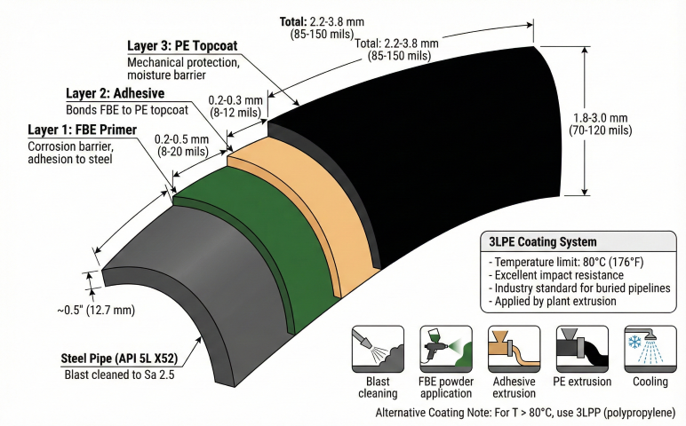
External Coatings (Pipeline)
3-Layer polyethylene (3LPE) coating system cross-section for buried pipeline protection.
Coating Type
Typical Thickness
Temperature Limit
Application
Cost ($/ft² typical)
3-Layer polyethylene (3LPE)
80-120 mils
140°F
Standard for buried pipelines; FBE + adhesive + PE
$5-8
3-Layer polypropylene (3LPP)
100-150 mils
250°F
High-temp pipelines, offshore; better than 3LPE for T > 140°F
$8-12
Fusion bonded epoxy (FBE)
12-20 mils (single), 24-40 mils (dual)
250°F
Moderate soil conditions; lower impact resistance than 3LPE
$3-5
Coal tar enamel
100-200 mils
140°F
Legacy coating; good performance but carcinogenic (avoid)
$4-6
Tape wrap (polyethylene)
40-80 mils
120°F
Field joints, repairs; lower quality than plant-applied
$2-4
Cathodic Protection
Cathodic Protection (CP) for External Corrosion:
External coating + CP = industry standard for buried pipelines.
Coating provides primary barrier; CP protects coating holidays (defects).
Impressed Current CP:
Rectifier supplies DC current to pipeline (cathode).
Anodes (graphite, MMO) buried near pipeline.
Current requirement:
I = (Coating_area × current_density) / coating_efficiency
Typical current density: 0.5-2 mA/ft² (bare pipe)
Coating efficiency: 95-99.5% (well-coated pipe)
For 10 miles of 24" pipe with 99% coating efficiency:
Coating area = π × 2 ft × 52,800 ft = 331,000 ft²
Bare area = 331,000 × 0.01 = 3,310 ft²
I = 3,310 ft² × 1 mA/ft² = 3.3 A
Rectifier size: 5-10 A capacity (with margin)
Sacrificial Anode CP:
Magnesium or zinc anodes buried along pipeline.
Galvanic current flows from anode to pipe (no external power).
Anode consumption:
Life (years) = (Anode_weight × Utilization% × Capacity) / (Current × 8760)
Where:
Capacity = 1300 A·hr/lb (magnesium), 780 A·hr/lb (zinc)
Utilization = 85% (typical)
Coating vs. Corrosion Allowance Economics
Economic Comparison:
Option 1: Corrosion allowance (no internal coating)
Extra wall thickness: 0.250 in
Pipe cost increase: ~$5-10 per ft (24" pipe)
10 miles: ~$250,000-500,000
Option 2: Internal epoxy coating
Coating cost: $5 per ft² × 6.3 ft² per ft = $31.50 per ft
10 miles: $1,660,000
Corrosion allowance is MUCH cheaper for pipelines.
However, internal coating may be required if:
- Corrosion rate > 30 mpy (CA would be excessive)
- Flow assurance (reduce friction, prevent wax/hydrate deposition)
- Product purity (prevent iron contamination)
- Existing pipeline (can't add wall thickness)
For piping and vessels (small diameter, high surface area per volume):
Internal coating is often more economical than CA.
For gas gathering/transmission (dry gas, low corrosion):
Neither CA nor coating may be required (bare carbon steel).
Material Testing and Certification
Mill Test Report (MTR): Certifies chemical composition, mechanical properties, heat treatment, and test results for each heat/lot. Required for all pressure-containing materials.
Positive Material Identification (PMI): Field verification of alloy content using XRF analyzer. Ensures correct material installed (prevents mixing carbon steel with stainless).
Hardness testing: For sour service, verify HRC ≤ 22 in weld, HAZ, and base metal. Rockwell or Vickers tester; non-destructive.
Impact testing (CVN): Charpy V-notch specimens machined from pipe, tested at specified temperature. Required for low-temp service or per specification.
Hydrostatic testing: Proof test at 1.5 × MAOP for pipelines, 1.3 × design pressure for piping. Verifies no leaks and material adequacy.
Non-destructive examination (NDE): Radiography (RT), ultrasonic testing (UT), or phased-array UT (PAUT) for weld quality. Required percentage depends on class location and specification.
Documentation is critical: For regulatory compliance (DOT 49 CFR 192, API 5L), maintain MTRs, PMI reports, hardness test results, CVN data, and hydrostatic test records for the life of the pipeline. Inability to prove material compliance can result in regulatory violations, required hydrotesting, or even replacement.