Calculate gas expansion work recovery, expansion ratios, temperature drop, power generation from pressure letdown, and integration with compression systems for NGL recovery and cryogenic plants.
Gas expanders recover energy from high-pressure gas by expanding it through a turbine, producing shaft work while simultaneously cooling the gas. This process is fundamental to natural gas liquids (NGL) recovery and cryogenic gas processing.
NGL recovery
Turboexpander plants
Expand high-pressure gas to low temperature for ethane+ recovery (70-95% recovery).
Pressure letdown
Energy recovery
Recover work from pipeline pressure reduction instead of throttling (JT valve).
LNG plants
Refrigeration cycle
Expanders provide refrigeration duty in cascade and mixed refrigerant systems.
Air separation
Cryogenic cooling
Expand air to cryogenic temperatures for nitrogen/oxygen separation.
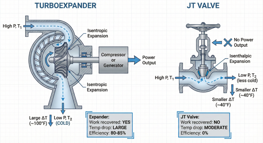
Expander vs. Joule-Thomson (JT) Valve
Parameter
Turboexpander
JT Valve (Throttling)
Process type
Isentropic expansion (ideal)
Isenthalpic expansion
Work recovery
Yes - shaft power output
No - energy lost as heat
Temperature drop
Larger (70-120°F per stage)
Smaller (30-50°F typical)
Efficiency
80-85% isentropic
0% (irreversible process)
Capital cost
High ($2-5M typical)
Low ($50-100k)
NGL recovery
70-95% ethane+
40-60% ethane+
Maintenance
Moderate (rotating equipment)
Low (no moving parts)
Turboexpander recovers shaft work and produces larger temperature drop compared to isenthalpic JT valve throttling.
Key Concepts
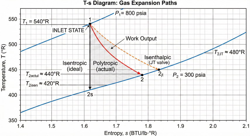
Isentropic expansion: Ideal expansion at constant entropy; actual expansion less efficient due to friction and heat transfer
Expansion ratio: Ratio of inlet to outlet pressure (P₁/P₂); typical range 2:1 to 4:1 per stage
Isentropic efficiency (η): Ratio of actual work to ideal isentropic work; 80-85% typical for turboexpanders
Expander brake: Device to absorb expander power - typically drives compressor, generator, or oil brake
Choke limit: Maximum flow through expander at sonic velocity; sets minimum downstream pressure
Economic justification: Turboexpanders justify capital cost when: (1) sufficient pressure drop available (>500 psi), (2) high gas flow rate (>10 MMscfd), (3) high NGL content (>3 GPM ethane+), or (4) power recovery value exceeds capital and maintenance costs. Payback typically 2-5 years.
2. Work Recovery Calculations
Gas expansion through a turboexpander recovers shaft work by extracting energy as the gas pressure decreases. The work recovered depends on inlet conditions, expansion ratio, gas properties, and expander efficiency.
Ideal Isentropic Work
Isentropic Expansion Work:
W_ideal = (ṁ × R × T₁ × Z_avg) / (MW × (k-1)) × [1 - (P₂/P₁)^((k-1)/k)]
Where:
W_ideal = Ideal shaft work (HP or kW)
ṁ = Mass flow rate (lb/hr or kg/hr)
R = Universal gas constant (1545 ft-lb/lbmol·°R or 8314 J/kmol·K)
T₁ = Inlet temperature (°R or K)
Z_avg = Average compressibility factor
MW = Molecular weight (lb/lbmol or kg/kmol)
k = Specific heat ratio (Cp/Cv)
P₂/P₁ = Pressure ratio (outlet/inlet)
Convert to horsepower:
HP_ideal = W_ideal / 33,000 (if W in ft-lb/min)
Or using flow rate in ACFM:
HP_ideal = (Q₁ × P₁ × k) / (229 × (k-1)) × [(P₂/P₁)^((k-1)/k) - 1]
Where Q₁ = Inlet volumetric flow (ACFM)
Actual Work with Efficiency
Actual Expander Work:
W_actual = W_ideal × η
Where:
η = Isentropic efficiency (0.75-0.85 typical)
For turboexpanders:
η = 0.80-0.85 (well-designed, high flow)
η = 0.75-0.80 (smaller units, lower flow)
η = 0.70-0.75 (older designs)
Efficiency affects both work and temperature:
T₂_actual = T₁ - η × (T₁ - T₂_ideal)
Where:
T₂_actual = Actual outlet temperature
T₂_ideal = Ideal isentropic outlet temperature
Polytropic Expansion Work
Polytropic Process (GPSA Method):
W_poly = (n/(n-1)) × Z_avg × R × T₁ × [1 - (P₂/P₁)^((n-1)/n)] / MW
Where:
n = Polytropic exponent
For EXPANSION (per GPSA Eq. 13-10):
n = k / [1 - ((k-1)/k) × (1 - η_poly)]
Note: This differs from compression where:
n_compression = k / [1 + ((k-1)/k) × (1/η_poly - 1)]
Polytropic efficiency for turboexpanders:
η_poly = 0.82-0.88 (well-designed units)
η_poly = 0.78-0.82 (smaller units)
Relationship between efficiencies:
η_isentropic ≈ η_poly × [(k-1)/k] / [(n-1)/n]
Polytropic efficiency is typically higher than isentropic for expanders.
T-s diagram: Actual polytropic expansion falls between ideal isentropic path and wasteful isenthalpic (JT) throttling.
Power Generation Options
Brake Type
Application
Efficiency
Capital Cost
Compressor (direct drive)
Recompression, refrigeration
95-98%
Low (integrated)
Electric generator
Power export to grid
92-95%
Moderate
Oil brake
Dissipate excess power
0% (heat only)
Low
Variable speed drive
Load matching
90-94%
High
Example Calculation 1: Turboexpander Work
Calculate power recovered from gas expansion in NGL plant:
Work per Standard Volume:
w = HP / Q_std
Where:
w = Specific work (HP/MMscfd)
Q_std = Standard volumetric flow rate
Typical values for turboexpanders:
- 800→300 psia: ~6-8 HP/MMscfd
- 1000→400 psia: ~7-9 HP/MMscfd
- 1200→500 psia: ~8-10 HP/MMscfd
Higher pressure drop → higher specific work
Richer gas (higher MW) → higher specific work
Practical sizing: Turboexpanders sized for maximum expected flow rate with turndown capability to 50-60% of design. Below turndown limit, bypass or recycle required. Oversizing by 10-15% provides operational margin. Typical commercial sizes: 500 HP, 1000 HP, 2000 HP, 5000 HP.
3. Expansion Ratio & Pressure Calculations
Expansion ratio selection balances temperature drop (for NGL recovery), work recovery, and mechanical constraints. Multi-stage expansion may be required for very high pressure drops.
Single-Stage Expansion Limits
Maximum Practical Expansion Ratio:
r_max = P₁ / P₂ ≤ 4:1 to 5:1 per stage
Limitations:
1. Mechanical stress on wheel (tip speed limits)
2. Temperature drop per stage (metallurgy)
3. Choke flow limit (sonic velocity)
4. Surge/efficiency considerations
Typical operating ranges:
Conservative: 2.5:1 to 3:1
Standard: 3:1 to 4:1
Aggressive: 4:1 to 4.5:1
For r > 5:1, use two stages in series
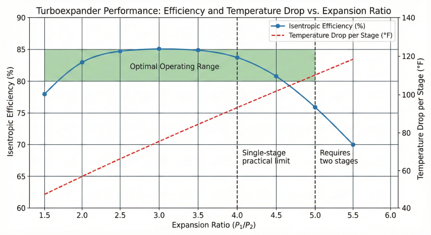
Turboexpander performance: Efficiency peaks at moderate ratios (2.5-4:1); higher ratios require multi-stage expansion.
Critical Pressure Ratio (Choking):
r_critical = (2/(k+1))^(k/(k-1))
For k = 1.25:
r_critical = (2/2.25)^5 = 0.565
This means:
P₂_min = P₁ × 0.565
Below this pressure ratio, flow becomes choked (sonic)
and further pressure reduction does not increase flow.
Example:
P₁ = 800 psia
P₂_min = 800 × 0.565 = 452 psia
Cannot expand below 452 psia in single stage without choking
Choking implications:
- Limits expansion ratio
- Fixes mass flow rate
- Requires oversized outlet piping
- May require two-stage expansion
Inlet Pressure Requirements
Minimum inlet pressure: Typically 400-500 psia for economic turboexpander operation
Optimal inlet pressure: 800-1200 psia for single-stage NGL recovery
High pressure systems: >1200 psia may require two-stage expansion
Pressure stability: ±5% variation acceptable; larger swings require control system
Turndown capability: Most expanders operate 50-100% of design flow; below 50% requires bypass
Example Calculation 2: Stage Pressure Selection
Design two-stage expander for high-pressure letdown:
Given:
Inlet: 1500 psia, 100°F
Final outlet: 250 psia
Flow: 60 MMscfd
Target: Equal work per stage
Step 1: Overall ratio
r_total = 1500 / 250 = 6:1
Step 2: Check single-stage feasibility
r_total = 6:1 exceeds 4:1 limit
→ Two stages required
Step 3: Equal ratio per stage
r₁ = r₂ = √6 = 2.45:1
Step 4: Interstage pressure
P₂ = P₁ / r₁ = 1500 / 2.45 = 612 psia
Or: P₂ = √(P₁ × P₃) = √(1500 × 250) = 612 psia ✓
Step 5: Verify each stage
Stage 1: 1500 → 612 psia (r = 2.45)
Stage 2: 612 → 250 psia (r = 2.45)
Both stages within 2.5:1 limit ✓
Step 6: Interstage reheating
If T after Stage 1 = -20°F
Reheat to 60°F before Stage 2
→ Increases Stage 2 work by ~15%
→ Prevents hydrate formation
4. Temperature Drop Prediction
Gas temperature decreases during expansion due to work extraction. Accurate temperature prediction is critical for NGL recovery optimization, hydrate prevention, and metallurgy selection.
Ideal Isentropic Temperature
Isentropic Temperature Drop:
T₂_ideal = T₁ × (P₂/P₁)^((k-1)/k)
Where:
T₂_ideal = Ideal outlet temperature (°R or K)
T₁ = Inlet temperature (°R or K)
P₂/P₁ = Pressure ratio
k = Specific heat ratio (Cp/Cv)
Temperature drop:
ΔT_ideal = T₁ - T₂_ideal
ΔT_ideal = T₁ × [1 - (P₂/P₁)^((k-1)/k)]
For k = 1.27 (natural gas):
(k-1)/k = 0.27/1.27 = 0.213
Actual Temperature with Efficiency
Actual Expander Outlet Temperature:
T₂_actual = T₁ - η × (T₁ - T₂_ideal)
Or:
ΔT_actual = η × ΔT_ideal
Where:
η = Isentropic efficiency (0.80-0.85)
Lower efficiency → less temperature drop
because less work extracted from gas
Alternative form:
T₂_actual = T₁ - η × T₁ × [1 - (P₂/P₁)^((k-1)/k)]
Temperature Drop Examples
Inlet P/T
Outlet P
Ratio
Ideal ΔT
Actual ΔT (η=0.82)
800 psia, 80°F
300 psia
2.67:1
118°F
97°F
1000 psia, 90°F
350 psia
2.86:1
125°F
103°F
1200 psia, 100°F
400 psia
3.0:1
130°F
107°F
1500 psia, 100°F
500 psia
3.0:1
130°F
107°F
600 psia, 70°F
250 psia
2.4:1
103°F
84°F
Assumes k = 1.27, isentropic efficiency = 82%
Hydrate Formation Concerns
Hydrate Temperature Prediction:
Gas hydrates form when:
1. Free water present
2. Temperature below hydrate point
3. Pressure above ~250 psia (approx)
Hydrate temperature (empirical):
T_hydrate ≈ 40°F + 0.015 × P
Where P = pressure (psia)
At 300 psia: T_hydrate ≈ 44.5°F
At 500 psia: T_hydrate ≈ 47.5°F
At 800 psia: T_hydrate ≈ 52°F
Prevention methods:
1. Dehydration upstream (< 7 lb H₂O/MMscf)
2. Methanol injection (500-2000 ppm)
3. Glycol injection (MEG, TEG)
4. Maintain T > T_hydrate + 10°F safety margin
Methanol depression:
ΔT = K × (wt% MeOH) / (100 - wt% MeOH)
K ≈ 2300°F (empirical constant)
Low-Temperature Metallurgy
Material
Minimum Temperature
Application
Carbon steel (SA-106)
-20°F
Standard expander casing
3.5% Ni steel
-50°F
Cold service upgrade
9% Ni steel
-100°F
Cryogenic applications
Stainless 304/316
-320°F
LNG service
Aluminum (5083)
-320°F
Lightweight cryogenic
Example Calculation 3: Temperature Prediction
Predict outlet temperature and check for hydrate risk:
Given:
Inlet: 900 psia, 85°F
Outlet: 320 psia
k = 1.27, η = 0.83
Gas: 0.6 lb H₂O/MMscf (dry)
Step 1: Inlet absolute temperature
T₁ = 85 + 460 = 545°R
Step 2: Pressure ratio
r = P₂/P₁ = 320/900 = 0.356
Step 3: Ideal outlet temperature
T₂_ideal = 545 × 0.356^0.213
T₂_ideal = 545 × 0.769
T₂_ideal = 419°R = -41°F
Step 4: Actual outlet temperature
T₂_actual = 545 - 0.83 × (545 - 419)
T₂_actual = 545 - 0.83 × 126
T₂_actual = 545 - 105
T₂_actual = 440°R = -20°F
Step 5: Check hydrate temperature
T_hydrate = 40 + 0.015 × 320 = 44.8°F
Step 6: Evaluate risk
T_outlet = -20°F < T_hydrate = 44.8°F
ΔT_margin = -20 - 44.8 = -64.8°F BELOW hydrate point
Conclusion: HIGH RISK of hydrate formation
Step 7: Mitigation required
Option 1: Inject methanol (1000 ppm typical)
Option 2: Preheat inlet to 120°F
Option 3: Increase dehydration to < 4 lb/MMscf
With preheat to 120°F:
T₁ = 580°R
T₂_actual = 475°R = 15°F
Still below hydrate point → methanol required
Temperature control: Outlet temperature cannot be independently controlled - it follows thermodynamic relationship with pressure ratio and efficiency. To increase outlet temperature: (1) increase inlet temperature, (2) reduce pressure ratio, or (3) reduce expander efficiency (inefficient but sometimes done via spoilers). Pre-expansion heating common practice.
5. Compression Integration
Turboexpanders are typically integrated with compressors to utilize recovered power and recompress low-pressure gas for sales or further processing. Proper integration optimizes energy efficiency and NGL recovery.
Expander-Compressor Configurations
Common Integration Schemes:
1. Direct-Coupled Configuration:
Expander shaft directly drives compressor
- Single rotating assembly
- No gearbox required
- Must match speeds (10,000-15,000 rpm typical)
- Power balance: HP_expander ≥ HP_compressor
2. Geared Configuration:
Gearbox between expander and compressor
- Independent speed optimization
- More flexible for different loads
- Gearbox efficiency: 98-99%
- Higher capital cost
3. Electric Generator/Motor:
Expander drives generator, motor drives compressor
- Maximum flexibility
- Can export excess power
- Lower mechanical efficiency (90-93%)
- Highest capital cost
Power Balance Calculations
Expander-Compressor Power Matching:
HP_compressor = HP_expander × η_mech - HP_losses
Where:
η_mech = Mechanical transmission efficiency
HP_losses = Bearing, seal, auxiliary losses (50-100 HP typical)
For direct-coupled:
η_mech = 0.97-0.98 (bearing losses only)
For geared:
η_mech = 0.98-0.99 (gearbox + bearings)
If HP_expander > HP_compressor:
- Install brake or generator to absorb excess
- Or recycle compressor discharge to increase load
If HP_expander < HP_compressor:
- Install helper motor (electric or turbine)
- Or reduce compressor load (lower flow/ratio)
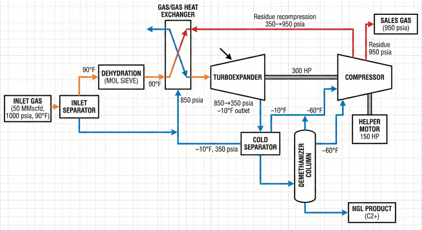
NGL Recovery Plant Configuration
Turboexpander NGL plant: Expander power offsets 60-80% of residue gas recompression; cold expansion enables high C2+ recovery.
Typical Turboexpander Plant Layout:
1. Gas Inlet → Separators (remove liquids)
2. Dehydration (TEG or molecular sieve)
3. Heat Exchangers (cool against cold tail gas)
4. Expander Inlet Chiller (optional propane refrigeration)
5. Turboexpander (expand to -20 to -60°F)
6. Cold Separator (remove condensed NGLs)
7. Demethanizer Column (separate C1 from C2+)
8. Side-stream Compressor (recompress residue gas)
9. Residue Gas Cooler (cool before sales)
10. NGL Stabilization (remove volatiles)
Expander integration points:
- Expander outlet → Demethanizer feed (cold separation)
- Compressor suction → Demethanizer overhead (CH₄-rich)
- Compressor discharge → Heat exchange → Sales gas
Energy integration:
- Expander work offsets ~60-80% of compression power
- Remaining power from electric motor or gas turbine
Residue Gas Recompression
Parameter
Typical Range
Notes
Suction pressure
200-400 psia
Expander outlet / demethanizer pressure
Discharge pressure
800-1200 psia
Sales gas or pipeline spec
Compression ratio
2.5:1 to 4:1
Single or two-stage
Power required
60-120% of expander power
Depends on flow split and ratio
Flow rate
70-90% of inlet flow
Reduced by NGL extraction
Example Calculation 4: Integrated System
Design expander-compressor system for NGL plant:
Given:
Inlet gas: 50 MMscfd, 1000 psia, 90°F
Expander outlet: 350 psia
NGL recovery: 15% of inlet flow (by volume)
Residue gas to sales: 950 psia
Step 1: Expander power (from prior calculation)
Assume: 7.5 HP/MMscfd for 1000→350 psia
HP_expander = 50 MMscfd × 7.5 HP/MMscfd
HP_expander = 375 HP
With efficiency η = 0.82:
HP_actual = 375 × 0.82 = 308 HP
Step 2: Residue gas flow
NGL extracted = 15% = 7.5 MMscfd equivalent
Residue flow = 50 - 7.5 = 42.5 MMscfd
Step 3: Compressor suction flow
Reduce to actual conditions (350 psia, ~-10°F)
Use same calculation approach
Q_compressor ≈ 42.5 MMscfd at base conditions
Step 4: Compressor power required
Ratio: r = 950 / 350 = 2.71:1
Assume: 8.0 HP/MMscfd for this ratio
HP_comp = 42.5 × 8.0 = 340 HP
With compressor efficiency η = 0.80:
HP_required = 340 / 0.80 = 425 HP
Step 5: Power balance
HP_expander = 308 HP (available)
HP_comp_required = 425 HP
HP_deficit = 425 - 308 = 117 HP
Step 6: Helper motor sizing
Mechanical losses ≈ 5% = 21 HP
Total helper motor = 117 + 21 = 138 HP
Select: 150 HP electric motor
Configuration:
- Expander provides 308 HP
- Helper motor provides 150 HP
- Total available: 458 HP
- Compressor uses: 425 HP
- Margin: 33 HP (7.8%)
Alternative: Reduce sales pressure to 900 psia
Reduces compression ratio to 2.57:1
HP_comp reduces by ~8% → No helper motor needed
Temperature control: Inlet heater adjusts for hydrate prevention and NGL recovery optimization
Pressure control: Sales gas pressure controller adjusts compressor discharge
Load sharing: Multiple expander-compressor trains share load via common discharge header
Design philosophy: Size expander for maximum expected flow. Size compressor for average residue gas flow at design pressure ratio. Provide helper motor for peak loads and startup. Include JT bypass valve for low-flow operation and emergency depressurization. Typical plant uptime: 95-98% with proper design and maintenance.