Pipeline drying removes residual water after hydrostatic testing before introducing hydrocarbons. Proper drying prevents hydrate formation, internal corrosion, and off-spec gas delivery.
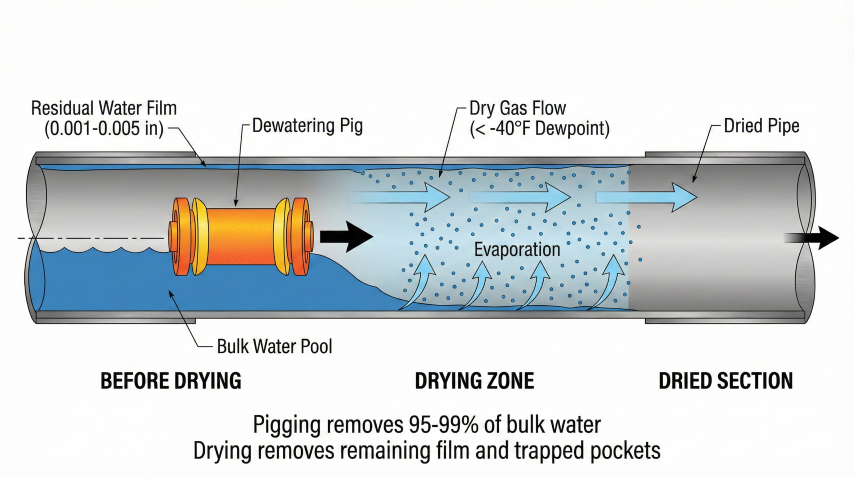
Pipeline drying process: Pigging removes 95-99% of bulk water, drying removes remaining film and trapped pockets.
Hydrate formation
Pipeline blockage
Water + gas at low temp/high pressure forms ice-like plugs.
Internal corrosion
Metal loss
Free water enables CO₂ and O₂ corrosion.
Product quality
Off-spec gas
Exceeds 7 lb/MMscf water content limit for sales gas.
Equipment damage
Slugging
Water slugs damage compressors and foul instruments.
Key Definitions
Dewpoint: Temperature at which water vapor condenses at given pressure
Water content: Mass of water per gas volume (lb/MMscf)
Hydrate formation temp: Temperature below which gas hydrates form (varies with pressure)
Example: A 10-mile, 12" pipeline holds ~7,400 bbl of water after hydrostatic testing. Pigging removes 95-99%, leaving ~75-370 bbl as film water and trapped pockets that must be removed by drying.
Method Comparison
Method
Cost
Time (10 mi)
Dewpoint
Best For
Air drying
$10-50k
5-20 days
-20 to -40°F
Onshore, budget-sensitive
N₂ drying
$50-200k
2-5 days
-40 to -80°F
Critical schedule, high purity
Vacuum
$20-100k
1-3 days
-60 to -100°F
Offshore, remote locations
Methanol slug
$5-30k
1-2 days
N/A*
Hydrate prevention, small lines
*Methanol absorbs water rather than achieving a specific dewpoint.
2. Drying Methods
Four primary methods for pipeline drying, each suited to different project requirements.
Air Drying
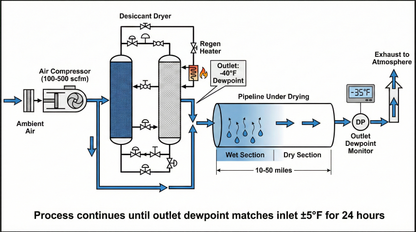
Air drying system schematic: Process continues until outlet dewpoint matches inlet ±5°F for 24 hours.
Process:
1. Pig to remove bulk water (95-99%)
2. Introduce dry air at -40°F dewpoint or lower
3. Circulate continuously, monitor outlet dewpoint
4. Complete when outlet matches inlet ±5°F for 24 hrs
Equipment: Compressor + desiccant dryer (100-500 scfm)
Advantages: Low cost, simple, no permits
Disadvantages: Slow (5-20 days), weather-dependent
Nitrogen Drying
Process:
1. Pig to remove bulk water
2. Circulate dry N₂ (-60°F to -100°F dewpoint)
3. Monitor outlet dewpoint
4. Can combine with pressure testing
N₂ Consumption:
Volume = Pipeline volume × 5-10 changes (for -40°F)
× 10-20 changes (for -60°F)
Cost Example: 10 mi × 12" = 41,500 ft³
10 changes = 415,000 scf @ $0.15/scf = $62,000
Advantages: Fast, very low dewpoints, inert
Disadvantages: High cost, asphyxiation hazard
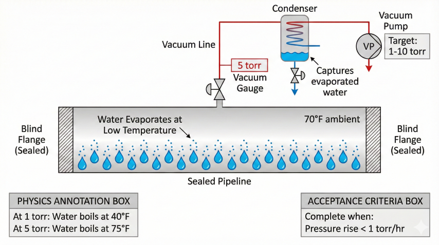
Vacuum Drying
Vacuum drying system: Water evaporates at low temperature under vacuum. Complete when pressure rise < 1 torr/hr.
Principle: Water boils at low temp under vacuum
At 1 torr (0.02 psia): Water boils at 40°F
At 5 torr (0.1 psia): Water boils at 75°F
Process:
1. Pig and seal pipeline (blind flanges)
2. Pull vacuum to 1-10 torr
3. Hold while water evaporates
4. Pressure rise test: <1 torr/hr = dry
Advantages: Fastest (1-3 days), no consumables
Disadvantages: Must be sealed, collapse risk
Methanol Slug Treatment
Principle: Methanol absorbs water (0.7 lb H₂O per lb MeOH)
Process:
1. Calculate water to remove from GPSA charts
2. Size methanol slug (typically 20-40% of pipe volume)
3. Push slug through with dry gas or nitrogen
4. Collect methanol/water mixture at downstream end
Best for: Gathering lines, hydrate prevention
Caution: Toxic/flammable - full PPE required
Dewatering Pigs
Run before drying to remove 90-99% of bulk water:
Pig Type
Removal
Application
Medium-density foam
70-90%
Initial pass
High-density foam
85-95%
Second pass
Bi-directional + squeegee
95-99%
Final dewatering
Best practice: Run 2-3 pigs in sequence before drying to minimize residual water.
3. Drying Calculations
Residual Water Estimation
After pigging (95-99% removed):
Film method: M = π × D × L × t × ρ
Where t = 0.001-0.005" film thickness
Example - 10 mi × 12" pipe:
M = π × 1.0 ft × 52,800 ft × 0.000167 ft × 62.4 lb/ft³
M = 1,730 lb ≈ 200 gallons residual water
Water Content from GPSA
Water content of natural gas vs temperature at various pressures. Source: GPSA.
Temp (°F)
100 psia
500 psia
1000 psia
-40
2.0
0.6
0.35
-20
5.5
1.4
0.8
40
34
7.8
4.3
80
111
26
14
Water content in lb/MMscf. Source: GPSA.
Methanol Requirements
MMeOH = (Wvapor + Wresidual) / (0.7 × P)
Where:
Wvapor = Vapor-phase water = (Winitial - Wtarget) × V
Wresidual = Residual free water after pigging (typically 1-2% of pipe volume)
0.7 = Methanol absorption capacity (lb H₂O/lb MeOH)
P = Methanol purity (fraction, e.g. 1.0 for 100%)
Example:
10 mi × 12" at 500 psia, 80°F → -20°F dewpoint
W_initial = 26 lb/MMscf, W_target = 1.4 lb/MMscf
V = 0.041 MMscf
Vapor water = (26 - 1.4) × 0.041 = 1.0 lb
Residual water (1.5% of 310,000 gal × 8.34 lb/gal) ≈ 38,800 lb
Total water = 1.0 + 38,800 ≈ 38,800 lb
Methanol = 38,800 / 0.7 = 55,400 lb = 8,360 gal
Note: Residual free water dominates methanol requirements.
Vapor-phase water is negligible in comparison for post-hydrotest drying.
Drying Time Estimates
Method
5 mi pipe
10 mi pipe
20 mi pipe
Air drying
3-10 days
5-20 days
10-30 days
N₂ drying
1-3 days
2-5 days
4-10 days
Vacuum
12-24 hr
24-48 hr
48-72 hr
Schedule contingency: Add 50-100% to calculated time. Weather, equipment issues, and higher-than-expected water extend actual duration.
4. Dewpoint Specifications
Dewpoint requirements based on hydrate formation temperature and operating conditions.
Hydrate Formation Temperature
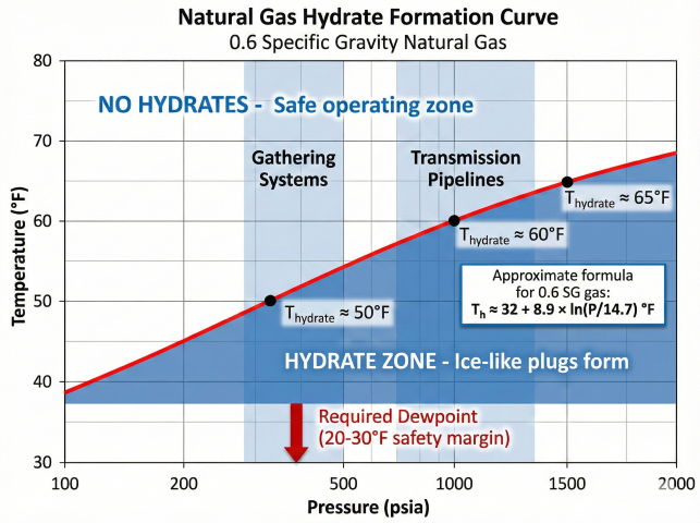
Natural gas hydrate formation curve. Conservative approximation: Th ≈ 32 + 8.9 × ln(P/14.7) °F for 0.6 SG gas.
Conservative approximation for natural gas (0.6 SG):
Th ≈ 32 + 8.9 × ln(P/14.7) °F
At 500 psia: Th ≈ 63°F
At 1,000 psia: Th ≈ 70°F
At 1,500 psia: Th ≈ 73°F
Note: This simplified formula overpredicts hydrate temperature
by 8-13°F vs the Katz gravity chart, erring on the safe side.
Required dewpoint:
Dewpoint < Tmin - Safety margin
Standard margin: 20-30°F below min operating temp
Industry Standard Dewpoints
Service
Dewpoint Spec
Gathering (<500 psia)
-20°F @ operating P
Transmission (500-1000 psia)
-20°F to -40°F @ 1000 psia
High-pressure (>1000 psia)
-40°F @ operating P
Arctic service
-60°F to -80°F
Sales gas (contract)
7 lb/MMscf @ 14.7 psia
Pressure Effect on Dewpoint
Important: Dewpoint rises with pressure compression.
Gas at -20°F dewpoint @ 500 psia
→ Compressed to 1,000 psia
→ New dewpoint ≈ -10°F (rises ~10°F per 2× pressure)
Best practice: Specify dewpoint at MAOP
"Dewpoint ≤ -20°F at 1,200 psig"
Dewpoint vs. water content: Dewpoint is intuitive for operations (relates directly to hydrate risk). Water content (lb/MMscf) is used in contracts. Always specify pressure basis.
5. Verification & Testing
Confirm dewpoint meets specification before commissioning.
Dewpoint Measurement
Method
Accuracy
Application
Chilled mirror
±0.5-2°F
Lab standard, most accurate
Capacitance sensor
±3-5°F
Portable field use
Aluminum oxide
±2-5°F
Online monitors
Monitoring Procedure
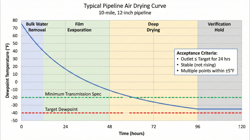
Typical pipeline air drying curve showing the four drying phases and acceptance criteria.
Sample points:
1. Inlet - verify dry gas supply
2. Outlet - primary measurement (slowest to dry)
3. Low points - water accumulates here
Acceptance criteria:
• Outlet dewpoint ≤ target for 24 hrs continuous
• Multiple sample points within ±5°F
• Dewpoint stable (not rising)
Sample system: 1/4" SS tubing, fast-loop flow,
coalescing filter, heat trace in cold weather
Troubleshooting
Problem
Cause
Solution
Dewpoint not decreasing
Low flow, wet inlet air
Increase flow, check dryer
Dewpoint stalls
Coating water release
Continue drying, heat if possible
Dewpoint rises after meeting spec
Leak, water intrusion
Check seals, sample lines
Cannot reach target
Insufficient inlet dewpoint
Add dryer stage
Documentation
Required records:
• Drying procedure and equipment
• Dewpoint logs (inlet/outlet readings)
• Calibration certificates
• Final acceptance readings (multiple points)
• Sign-off by company and contractor
Acceptance statement example:
"Pipeline dried to -20°F dewpoint at 1,000 psig.
Outlet readings averaged -23°F over 24-hr period."
Critical: Never commission based solely on calculated drying time. Always verify measured dewpoint at outlet meets spec for 24+ hours. Many hydrate failures occur from inadequate verification.