1. Flow Regimes
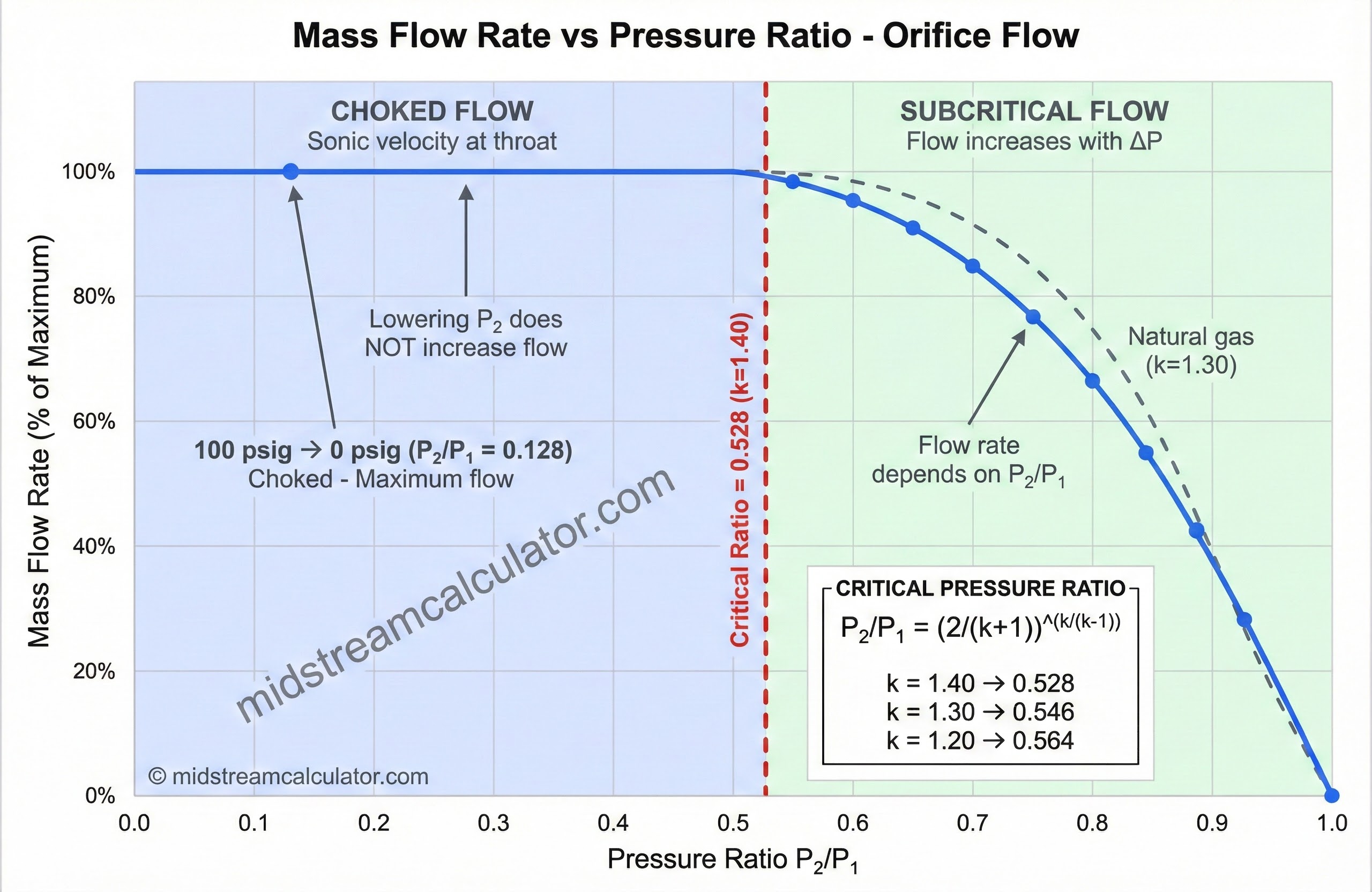
Gas flow through an orifice is either subcritical (downstream pressure affects flow) or critical/choked (flow limited by sonic velocity).
Critical Ratios by Gas
| Gas | k (Cp/Cv) | Critical Ratio | Y (choked) |
|---|---|---|---|
| Air, N₂, O₂ | 1.40 | 0.528 | 0.667 |
| Hydrogen | 1.41 | 0.527 | 0.669 |
| Methane | 1.31 | 0.545 | 0.651 |
| Natural Gas | 1.27–1.32 | 0.544–0.552 | 0.645–0.655 |
| CO₂ | 1.30 | 0.546 | 0.649 |
| H₂S | 1.32 | 0.544 | 0.653 |
| Steam | 1.33 | 0.543 | 0.655 |
| Propane | 1.13 | 0.575 | 0.615 |
Practical rule: Most blowdowns to atmosphere are choked. A 100 psig vessel venting to 0 psig has P₂/P₁ = 14.7/114.7 = 0.13, well below the critical ratio.
2. Design Equations
Gas Service — Choked Flow
Gas Service — Subcritical Flow
Liquid Service
Blowdown Time
3. Coefficients & Reference Data
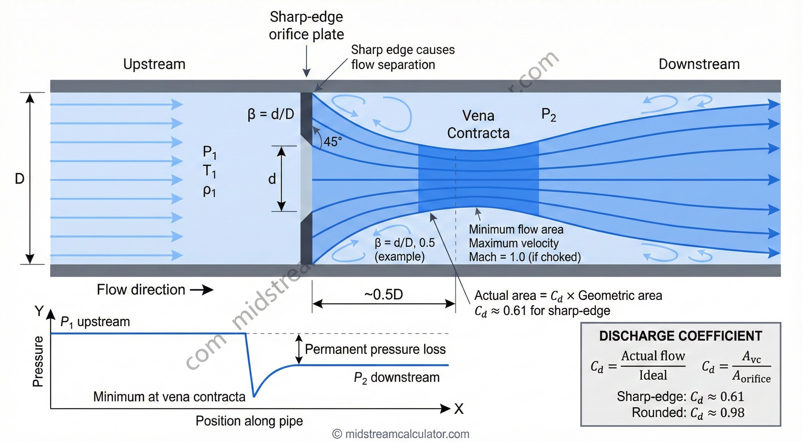
Discharge Coefficients
| Orifice Type | Cd | Application |
|---|---|---|
| Sharp-edge, corner taps | 0.61 | Standard drain orifice |
| Sharp-edge, flange taps | 0.60 | Metering orifice |
| Square-edge entrance | 0.82 | Pipe entrance |
| Rounded entrance (r/d>0.1) | 0.98 | Low-loss nozzle |
| Venturi / flow nozzle | 0.99 | Metering |
Typical Orifice Sizes
| Application | Typical Size | Design Consideration |
|---|---|---|
| Separator blowdown | 1" – 2" | Choked flow, noise |
| Pipeline blowdown | 0.5" – 1.5" | Line pack volume |
| Compressor scrubber | 0.75" – 1.5" | Auto-drain cycle |
| Tank drain (liquid) | 2" – 4" | Gravity flow |
Standard Orifice Sizes
| Diameter (in) | Area (in²) | Diameter (in) | Area (in²) |
|---|---|---|---|
| 0.250 | 0.0491 | 0.875 | 0.601 |
| 0.375 | 0.110 | 1.000 | 0.785 |
| 0.500 | 0.196 | 1.250 | 1.227 |
| 0.625 | 0.307 | 1.500 | 1.767 |
| 0.750 | 0.442 | 2.000 | 3.142 |
Expansion Factor Y (Choked Flow)
Use this table to find Y for choked flow based on gas specific heat ratio k.
| k (Cp/Cv) | Critical Ratio | Y (choked) | Typical Gas |
|---|---|---|---|
| 1.10 | 0.585 | 0.600 | Heavy hydrocarbons |
| 1.15 | 0.573 | 0.615 | Propane |
| 1.20 | 0.564 | 0.629 | Rich natural gas |
| 1.25 | 0.555 | 0.640 | — |
| 1.30 | 0.546 | 0.649 | Natural gas, CO₂ |
| 1.35 | 0.538 | 0.658 | — |
| 1.40 | 0.528 | 0.667 | Air, N₂, O₂ |
| 1.45 | 0.520 | 0.675 | — |
| 1.66 | 0.487 | 0.725 | Helium, Argon |
Y = √[k × (2/(k+1))^((k+1)/(k-1))]
Critical Flow Properties by Gas
| Gas | MW | k | Critical Ratio | Y |
|---|---|---|---|---|
| Air | 28.97 | 1.40 | 0.528 | 0.667 |
| Nitrogen (N₂) | 28.01 | 1.40 | 0.528 | 0.667 |
| Oxygen (O₂) | 32.00 | 1.40 | 0.528 | 0.667 |
| Methane (CH₄) | 16.04 | 1.31 | 0.545 | 0.651 |
| Natural Gas (0.65 SG) | 18.8 | 1.27–1.32 | 0.544–0.552 | 0.645–0.655 |
| Carbon Dioxide (CO₂) | 44.01 | 1.30 | 0.546 | 0.649 |
| Hydrogen Sulfide (H₂S) | 34.08 | 1.32 | 0.544 | 0.653 |
| Hydrogen (H₂) | 2.02 | 1.41 | 0.527 | 0.669 |
| Propane (C₃H₈) | 44.10 | 1.13 | 0.575 | 0.615 |
| Steam | 18.02 | 1.33 | 0.543 | 0.655 |
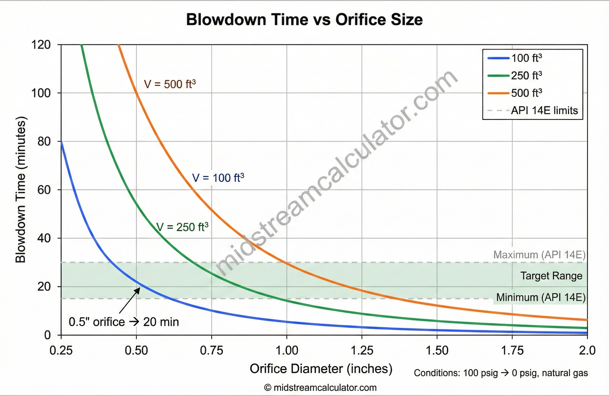
Quick Sizing Reference
Approximate blowdown times for natural gas (0.65 SG) from 100 psig to atmosphere at 80°F.
| Vessel Volume | 0.50" orifice | 0.75" orifice | 1.00" orifice | 1.50" orifice |
|---|---|---|---|---|
| 25 ft³ | 5 min | 2.2 min | 1.3 min | 0.6 min |
| 50 ft³ | 10 min | 4.5 min | 2.5 min | 1.1 min |
| 100 ft³ | 20 min | 9 min | 5 min | 2.2 min |
| 250 ft³ | 50 min | 22 min | 12.5 min | 5.5 min |
| 500 ft³ | 100 min | 45 min | 25 min | 11 min |
| 1000 ft³ | 200 min | 90 min | 50 min | 22 min |
Based on Cd = 0.61, choked flow. Times are approximate—use calculator for accurate sizing.
Blowdown Time Scaling
To adjust quick-sizing values for different conditions:
| Parameter Change | Effect on Time | Example |
|---|---|---|
| Double vessel volume | × 2.0 | 100→200 ft³: 20 min → 40 min |
| Double orifice area | ÷ 2.0 | 0.5"→0.7" (2× area): 20 min → 10 min |
| Double pressure | × 1.4 (approx) | 100→200 psig: 20 min → 28 min |
| Heavier gas (higher MW) | × √(MW₂/MW₁) | NG→Propane: 20 min → 31 min |
| Higher temperature | × √(T₂/T₁) | 80°F→200°F: 20 min → 22 min |
API 14E guidance: Size for 15-30 min blowdown (gas) or 30-60 min (liquid) unless process requirements dictate otherwise.
4. Worked Example
Problem: Size a blowdown orifice for a 100 ft³ separator at 100 psig to depressurize to atmosphere in 20 minutes.
Given
| Volume | V = 100 ft³ |
| Upstream pressure | P₁ = 114.7 psia |
| Downstream pressure | P₂ = 14.7 psia |
| Gas | Natural gas, SG = 0.65, k = 1.30 |
| Temperature | T = 80°F = 540°R |
| Target time | t = 20 min = 1200 s |
Solution
⚠ Notes: This simplified calculation uses average density. For accurate blowdown time, integrate over the pressure decay curve. Add 10-20% margin for fouling.
References
- API RP 14E – Offshore Platform Piping Systems
- ISO 5167-2 – Orifice Plates
- Crane Technical Paper 410
- GPSA, Section 6
Ready to use the calculator?
→ Launch Calculator