1. Overview & Purpose
Depressurizing systems provide rapid, controlled pressure reduction in vessels and pipelines during emergencies. Unlike pressure relief valves (which respond to overpressure), depressuring systems are typically activated manually or automatically to evacuate contents before equipment failure occurs.
Primary Applications
Fire Case
External Fire Exposure
Reduce pressure before fire weakens vessel wall and causes rupture. Most common depressuring scenario.
Emergency Shutdown
Process Upset
Controlled depressuring during major equipment failures, runaway reactions, or hazardous releases.
Maintenance
Safe Entry
Depressure equipment to atmospheric pressure for inspection, repair, or turnaround activities.
Pipeline Isolation
Section Blowdown
Evacuate pipeline segments between block valves for maintenance or emergency isolation.
Key Terminology
- Blowdown valve (BDV): Large valve (full-bore ball or gate) opened to initiate rapid depressurization
- Depressuring rate: Pressure reduction per unit time, typically expressed as time to reach target pressure
- MAWP: Maximum Allowable Working Pressure — highest pressure permitted at vessel top per ASME code
- Environment factor (F): Multiplier (0–1) accounting for fire protection measures on vessel
- Joule-Thomson cooling: Temperature drop during gas expansion through restriction (valve/orifice)
- MDMT: Minimum Design Metal Temperature — lowest temperature at which material is rated
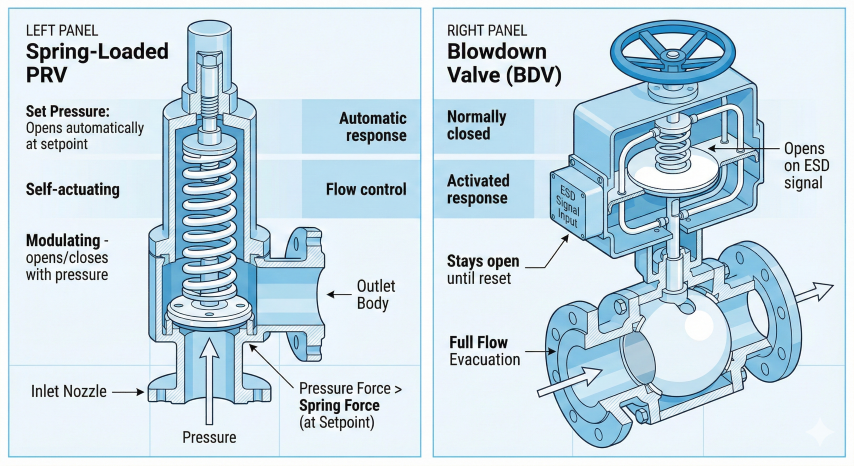
2. Relief vs. Blowdown Valves
Relief valves and blowdown valves serve fundamentally different purposes. Both are typically required on pressure vessels, and understanding their distinct functions is essential for proper safety system design.
Functional Comparison
| Feature | Relief Valve (PRV/PSV) | Blowdown Valve (BDV) |
|---|---|---|
| Primary purpose | Prevent overpressure (automatic protection) | Emergency depressurization (rapid evacuation) |
| Activation | Automatic — opens at set pressure | Manual or ESD signal — operator/system initiated |
| Flow capacity | Sized for specific relief scenarios | Sized for rapid vessel evacuation |
| Operating mode | Opens/closes as pressure fluctuates | Opens fully, stays open until manually reset |
| Valve type | Spring-loaded safety valve (ASME certified) | Full-bore ball, gate, or plug valve |
| Regulatory requirement | Mandatory per ASME Section VIII | Required for fire case per API 521 |
| Testing/certification | ASME code stamp, periodic recertification | Functional testing, no ASME certification |
Why Both Are Required
Consider a vessel exposed to fire:
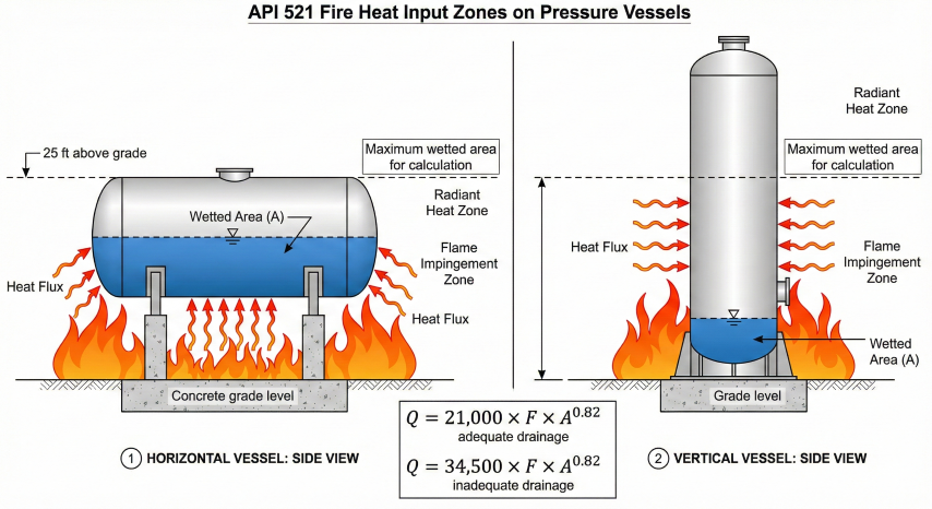
3. API 521 Fire Case Requirements
API Standard 521 "Pressure-Relieving and Depressuring Systems" provides the industry-standard methodology for designing depressurization systems, particularly for fire case scenarios.
Fire Case Depressurization Criteria
Per API 521 Section 5.15.2.2:
Fire Heat Input Calculation
API 521 provides correlations for heat absorbed by wetted vessel surfaces during fire exposure:
Environment Factor (F)
| Fire Protection Measure | F Factor | Notes |
|---|---|---|
| Bare vessel (no protection) | 1.0 | Base case — no credit |
| Approved fireproofing | 0.3 | UL-listed, minimum 2-hour rating |
| 1" mineral fiber insulation | 0.30 | With stainless steel jacket |
| 2" mineral fiber insulation | 0.15 | With stainless steel jacket |
| 4" mineral fiber insulation | 0.075 | With stainless steel jacket |
| Water application (deluge) | 1.0* | *Credit through different mechanism |
| Underground/buried vessel | 0.0 | No fire exposure |
Material Temperature Limits
| Material | MDMT (Min) | Max Design Temp | Approx. Rupture Temp |
|---|---|---|---|
| Carbon Steel (SA-516 Gr 70) | -20°F | 700°F | ~1100°F |
| Low Alloy Steel (SA-387) | -50°F | 850°F | ~1150°F |
| Stainless Steel 304/316 | -320°F | 1000°F | ~1500°F |
4. Sizing & Design
Critical Flow Through Orifice
Blowdown flow is typically choked (sonic) at the orifice. Per API 520 Part I:
Critical Pressure Ratio
Flow is critical (choked) when downstream pressure is below the critical value:
API 526 Standard Orifice Sizes
| Letter | Area (in²) | Inlet × Outlet | Typical Application |
|---|---|---|---|
| D | 0.110 | 1" × 2" | Small separators, instruments |
| E | 0.196 | 1" × 2" | Small vessels |
| F | 0.307 | 1½" × 2½" | Medium separators |
| G | 0.503 | 1½" × 3" | Medium vessels |
| H | 0.785 | 2" × 3" | Large separators |
| J | 1.287 | 2½" × 4" | Large vessels |
| K | 1.838 | 3" × 4" | Columns, reactors |
| L | 2.853 | 3" × 6" | Large columns |
| M | 3.60 | 4" × 6" | Very large vessels |
| N | 4.34 | 4" × 6" | Very large vessels |
| P | 6.38 | 4" × 6" | Major equipment |
| Q | 11.05 | 6" × 8" | Large reactors, drums |
| R | 16.00 | 6" × 10" | Pipeline depressuring |
| T | 26.00 | 8" × 10" | Pipeline blowdown |
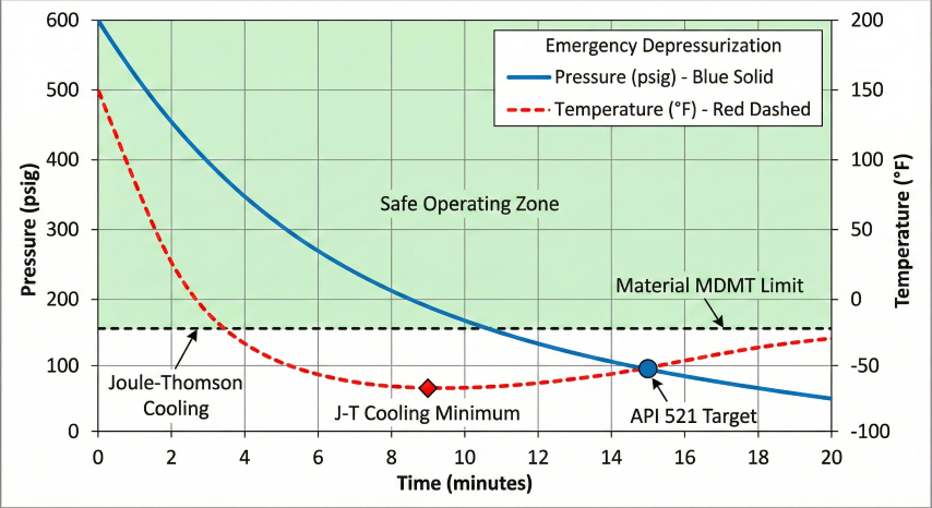
Joule-Thomson Cooling
Gas expanding through the blowdown valve experiences significant temperature drop:
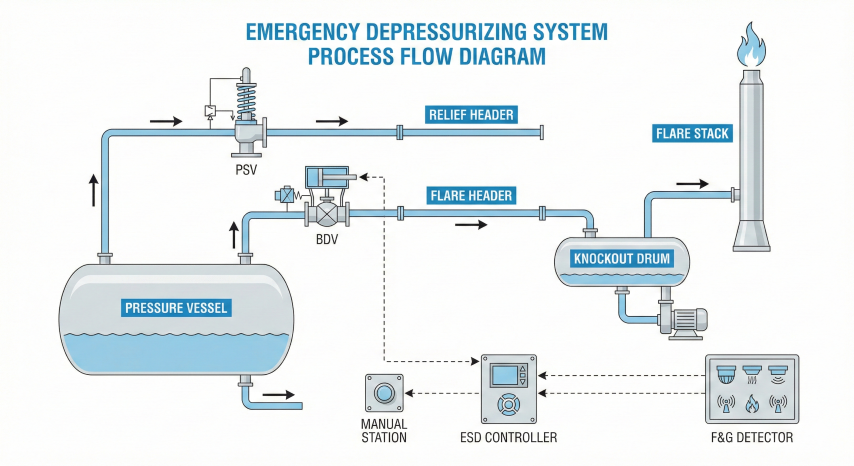
5. System Integration
Flare System Components
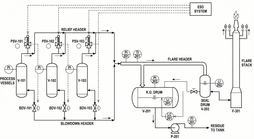
Depressurization systems typically discharge to a flare system for safe combustion:
- Flare header: Collects flow from all relief and blowdown sources; sized for maximum simultaneous relief
- Knockout drum: Removes liquid carryover; sized for depressuring liquid surge
- Flare stack: Elevates flame for thermal radiation safety; height from radiation analysis
- Flare tip: Smokeless combustion (steam or air-assisted); continuous pilots
- Liquid seal drum: Prevents flashback into header (if used)
ESD Integration
| Activation Method | Typical Application | Response Time |
|---|---|---|
| Manual pushbutton | Operator-initiated emergency | ~30–60 seconds |
| Fire detection (F&G) | Automatic fire response | <10 seconds |
| Gas detection (>60% LEL) | Leak/release response | <10 seconds |
| Fusible link | Passive heat-activated | ~60–120 seconds |
Common Design Issues
- Undersized blowdown valve: Fails to meet 15-minute target — always include margin
- Ignoring J-T cooling: Material embrittlement at low temperature — verify MDMT
- Inadequate piping support: High reaction forces during blowdown — properly anchor
- Flare overload: Depressuring exceeds flare capacity — verify flare hydraulics
- Single point of failure: No backup actuation — use redundant solenoids
- Icing at valve: Hydrate/ice formation blocking flow — consider heating or methanol
Testing & Maintenance
| Frequency | Activity |
|---|---|
| Monthly | Visual inspection, position indication check, leak survey |
| Quarterly | Partial stroke test (if possible), actuator lubrication, ESD logic test |
| Annually | Full stroke test (during shutdown), limit switch calibration |
| Every 5 years | Valve disassembly, seat/seal inspection, hydrostatic test |
Ready to use the calculator?
→ Launch Calculator