Compressors increase gas pressure by imparting mechanical energy. Selection depends on flow rate, pressure ratio, gas properties, and operational requirements.
Positive Displacement
Reciprocating (API 618)
50–10,000 ACFM, ratio 2–4:1/stage. High efficiency, variable flow capability.
Dynamic
Centrifugal (API 617)
2,000–200,000+ ACFM, ratio 1.5–3:1/stage. High reliability, continuous duty.
Positive Displacement
Screw (API 619)
500–12,000 ACFM, ratio 2–6:1. Simple, tolerates dirty gas.
Dynamic
Axial
50,000–1,000,000+ ACFM, ratio 1.1–1.2/stage. Highest efficiency at large scale.
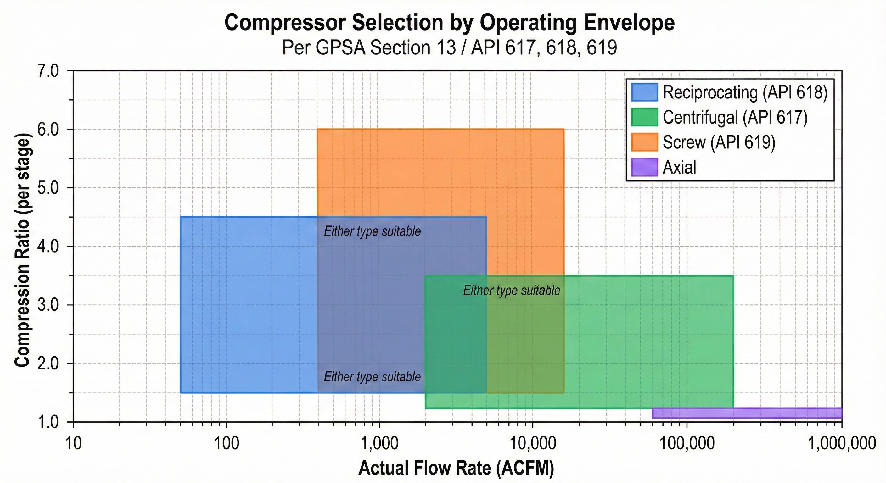
Flow rate vs pressure ratio selection map for compressor types.
Selection Summary
Type
Flow Range
Max Ratio/Stage
ηp Range
Best Application
Reciprocating
50–10,000 ACFM
4.0:1
82–88%
High ratio, variable flow
Centrifugal
2,000–200,000 ACFM
3.0:1
75–85%
High flow, continuous
Screw
500–12,000 ACFM
6.0:1 (oil-flooded)
70–78%
Moderate flow, simplicity
Axial
>50,000 ACFM
1.2:1
85–90%
Very high flow, LNG
Rule of thumb: Use reciprocating for high pressure ratios and variable loads; centrifugal for large continuous flows; screw for simplicity and dirty gas; axial for very high flows (>50,000 ACFM).
2. Compression Thermodynamics
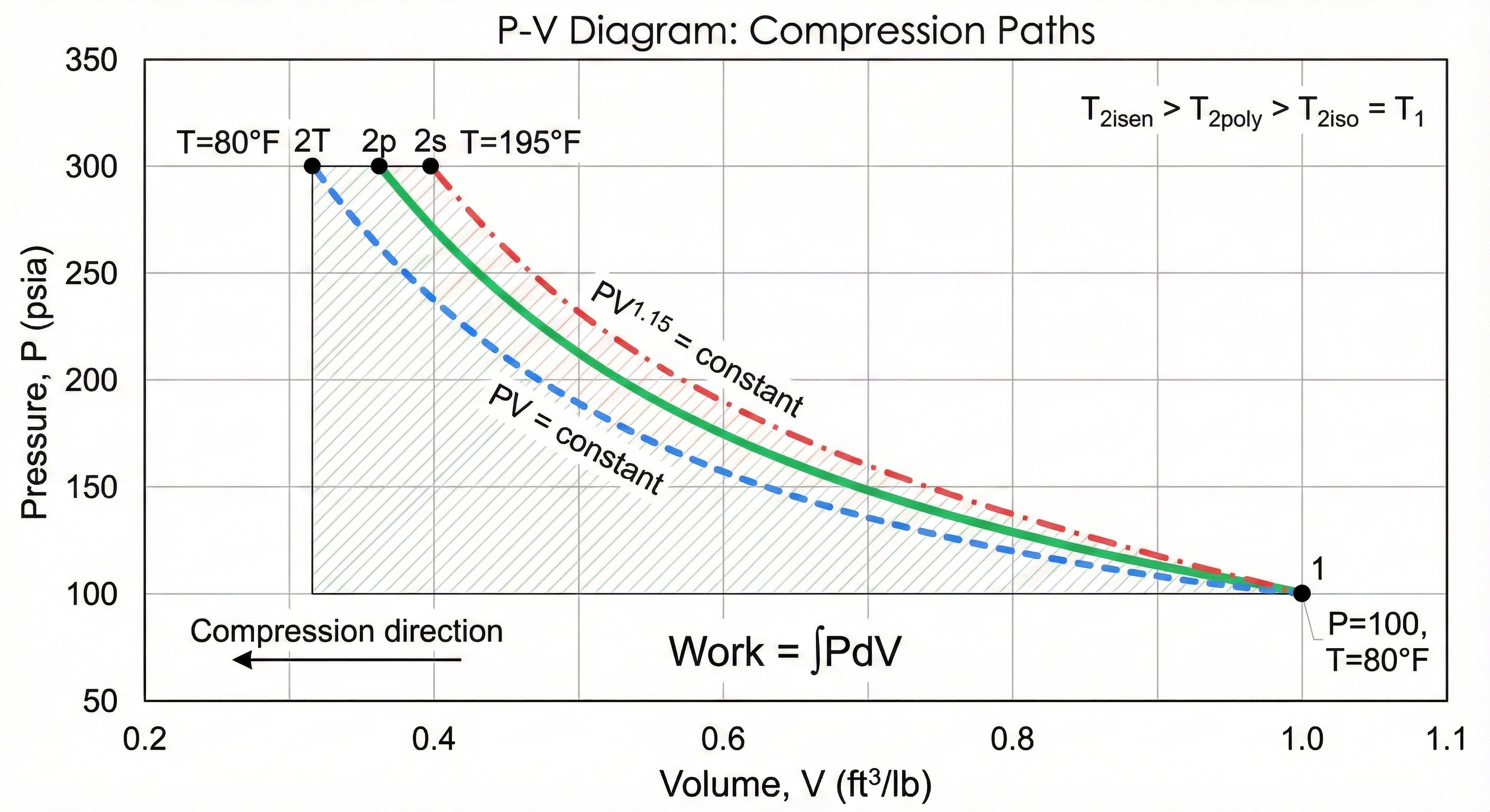
Gas compression can follow three idealized paths. Real compressors approximate polytropic compression.
P-V diagram comparing isothermal, polytropic, and isentropic compression paths.
Isentropic (Adiabatic Reversible) Compression
No heat transfer, reversible process. Represents ideal dynamic compressor behavior.
Isentropic Relations:
PVk = constant
Temperature ratio:
T₂/T₁ = (P₂/P₁)(k-1)/k = r(k-1)/k
Where:
k = Cₚ/Cᵥ (specific heat ratio)
r = P₂/P₁ (compression ratio)
T = absolute temperature (°R)
P = absolute pressure (psia)
For natural gas: k ≈ 1.26–1.31 (function of composition and T)
Polytropic Compression (Real Process)
Accounts for heat transfer and irreversibilities. The polytropic exponent n lies between 1 (isothermal) and k (isentropic).
Polytropic Relations:
PVn = constant
Temperature ratio:
T₂/T₁ = (P₂/P₁)(n-1)/n = r(n-1)/n
Polytropic exponent from efficiency:
n/(n-1) = (k/(k-1)) × ηp
Solving for n:
n = (k × ηp) / (k × ηp - k + 1)
For ηp = 0.80 and k = 1.28:
n = (1.28 × 0.80) / (1.28 × 0.80 - 1.28 + 1) = 1.024/0.744 = 1.376
Temperature limits: Reciprocating (API 618): 350°F max (valve life). Centrifugal (API 617): 450°F typical. Exceeding limits requires intercooling.
3. Power Calculations
Compressor power is calculated from head (energy per unit mass) and mass flow rate. GPSA Section 13 provides standard methods.
Head Calculation
Polytropic Head (GPSA Eq. 13-4):
Hp = (Zavg × R × T₁ / MW) × (n/(n-1)) × [r(n-1)/n - 1]
Where:
Hp = polytropic head (ft-lbf/lbm)
Zavg = average compressibility factor
R = 1545.35 ft-lbf/(lbmol·°R)
T₁ = suction temperature (°R)
MW = molecular weight (lb/lbmol)
n = polytropic exponent
r = compression ratio
Isentropic Head:
Hisen = (Zavg × R × T₁ / MW) × (k/(k-1)) × [r(k-1)/k - 1]
Gas Horsepower
Gas Horsepower (from head):
GHP = (ṁ × Hp) / 33,000
Where:
GHP = gas horsepower (HP)
ṁ = mass flow rate (lb/min)
Hp = polytropic head (ft-lbf/lbm)
33,000 = ft-lbf/min per HP
Mass flow from standard flow:
ṁ = Qstd × (Pstd × MW) / (R × Tstd)
Where Qstd in SCF/min at 14.696 psia, 60°F
Brake Horsepower
Shaft Power:
BHP = GHP / ηmechDriver Power (with API 10% margin):
Driver HP = BHP × 1.10
Typical mechanical efficiencies:
• Centrifugal: 0.96–0.99
• Reciprocating: 0.90–0.95
• Screw: 0.92–0.96
GPSA Simplified Power Equation
GPSA Direct Power Calculation:
HP = (Q × Z × T₁ × k) / (C × (k-1) × ηp) × [r(k-1)/k - 1]
Where:
Q = flow rate (MMSCFD at 14.696 psia, 60°F)
T₁ = suction temperature (°R)
Z = compressibility factor at suction
C = 3.027 × 10⁻⁵ (constant for units shown)
ηp = polytropic efficiency
Quick estimate (natural gas, k ≈ 1.28):
HP ≈ 90 × QMMSCFD × SG × [r0.22 - 1] / ηp
Example Calculation
Given:
Q = 50 MMSCFD natural gas (SG = 0.65, MW = 18.8)
P₁ = 400 psig = 414.7 psia
P₂ = 900 psig = 914.7 psia
T₁ = 90°F = 549.67°R
k = 1.28, Z = 0.88, ηp = 0.80, ηmech = 0.97
Step 1: Compression ratio
r = 914.7 / 414.7 = 2.206
Step 2: Polytropic exponent
n = (1.28 × 0.80) / (1.28 × 0.80 - 1.28 + 1) = 1.024 / 0.744 = 1.376
Step 3: Polytropic head
Hp = (0.88 × 1545 × 549.67 / 18.8) × (1.376/0.376) × [2.2060.273 - 1]
Hp = 39,800 × 3.66 × [1.244 - 1] = 39,800 × 3.66 × 0.244
Hp = 35,500 ft-lbf/lbm
Step 4: Mass flow
SCFM = 50 × 10⁶ / 1440 = 34,722 SCF/min
ṁ = 34,722 × 14.696 × 144 × 18.8 / (1545 × 519.67) = 1,660 lb/min
Step 5: Gas horsepower
GHP = (1,660 × 35,500) / 33,000 = 1,785 HP
Step 6: Brake and driver power
BHP = 1,785 / 0.97 = 1,840 HP
Driver = 1,840 × 1.10 = 2,024 HP → Select 2,250 HP motor
4. Efficiency Definitions & Conversions
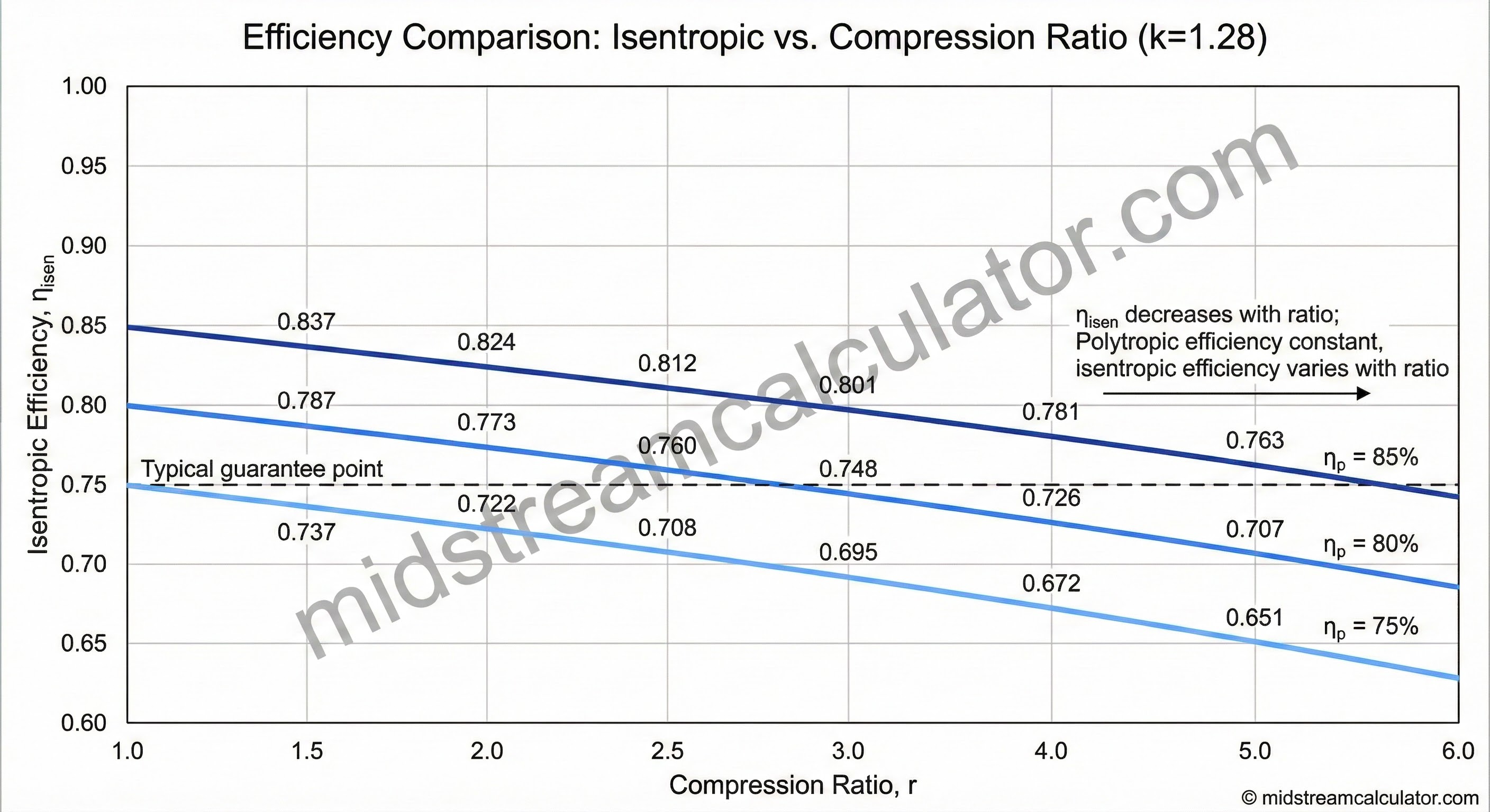
Polytropic efficiency is preferred for compressor selection as it remains constant regardless of pressure ratio. Isentropic efficiency varies with ratio.
Polytropic Efficiency
Definition:
ηp = Ideal work (differential) / Actual work (differential)
From measured data:
ηp = [(k-1)/k] × ln(r) / ln(T₂/T₁)
Typical values:
• Large centrifugal (>10,000 HP): 78–85%
• Small centrifugal (<3,000 HP): 72–78%
• Reciprocating: 82–88%
• Screw (oil-flooded): 70–78%
• Axial: 85–90%
Polytropic efficiency is independent of pressure ratio—
same value applies whether ratio is 1.5 or 3.0.
Isentropic Efficiency
Definition:
ηisen = Isentropic work / Actual work
From temperatures:
ηisen = (T₂,isen - T₁) / (T₂,actual - T₁)
From heads:
ηisen = Hisen / Hactual
Isentropic efficiency DECREASES as pressure ratio increases
for the same machine. Not suitable for comparing compressors
at different operating points.
Efficiency Conversion
Isentropic to Polytropic:
ηp = ln(r(k-1)/k) / ln[1 + (r(k-1)/k - 1) / ηisen]
Polytropic to Isentropic:
ηisen = [r(k-1)/k - 1] / [r(n-1)/n - 1]
Where n is found from: n/(n-1) = (k/(k-1)) × ηpExample:
Given ηisen = 0.75, r = 2.5, k = 1.28
r0.219 = 1.234
ηp = ln(1.234) / ln[1 + (0.234/0.75)]
ηp = 0.210 / ln(1.312) = 0.210 / 0.272 = 0.77 (77%)
Isentropic efficiency vs compression ratio at constant polytropic efficiencies.
Always use polytropic efficiency when comparing compressors or evaluating multi-stage machines. Isentropic efficiency is acceptable only for quick single-stage estimates at known operating point.
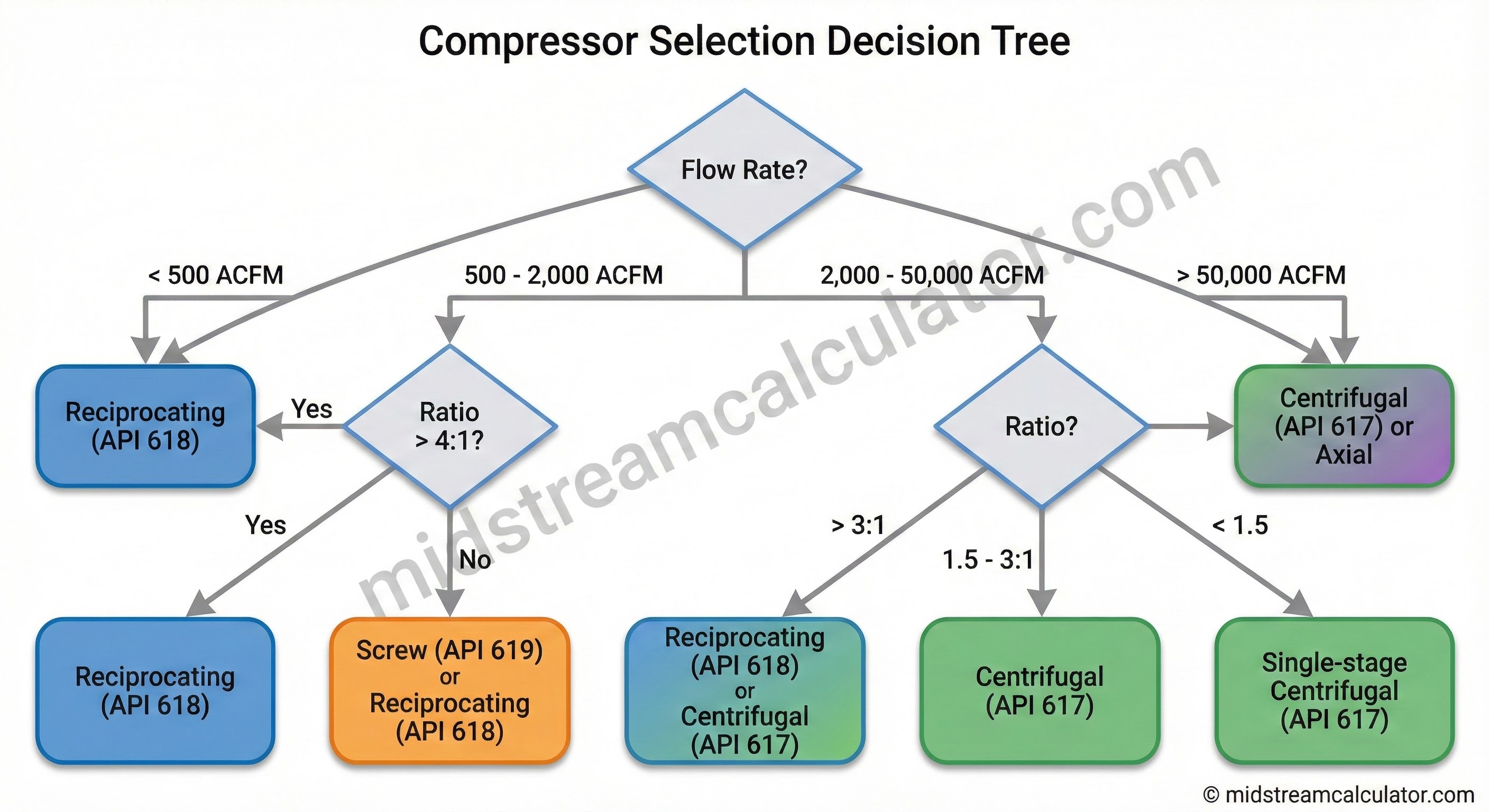
Compressor selection flowchart by flow rate and pressure ratio.
Staging Guidelines
Optimal Staging (Equal Work):
For overall ratio rtotal with N stages:
rstage = rtotal1/NStage count estimate:
N = ln(rtotal) / ln(rmax,stage)
Example:
rtotal = 10:1, centrifugal (rmax = 2.5:1)
N = ln(10) / ln(2.5) = 2.30 / 0.92 = 2.5 → Use 3 stages
rstage = 101/3 = 2.15:1 per stage
Intercooling:
Between stages, cool discharge back to near suction T.
Power savings: 10–20% vs. no intercooling.
6. Practical Design Considerations
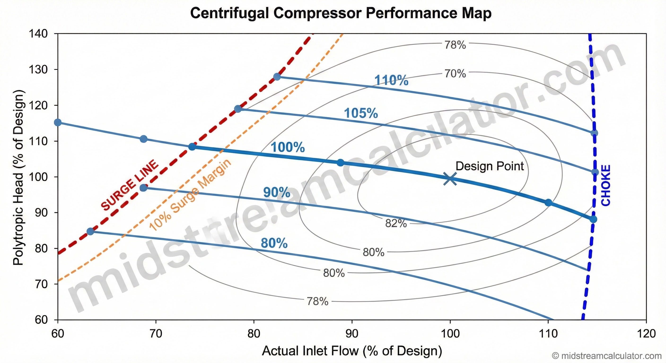
Surge Protection (Centrifugal)
Surge occurs when flow drops below the minimum stable point, causing flow reversal, vibration, and potential damage.
Centrifugal compressor head vs flow map with surge and choke lines.
Valve unloaders: Hold suction valve open → 25%, 50%, 75%, 100% steps
Speed control: VFD or variable speed driver → 10–100% continuous
Volumetric Efficiency (Reciprocating)
Volumetric Efficiency:
ηv = 1 - C × [r1/k - 1] - L
Where:
C = clearance ratio (typically 0.05–0.15)
r = compression ratio
k = specific heat ratio
L = losses (typically 0.03–0.05)
Higher ratio → lower volumetric efficiency.
Limits practical single-stage ratio to ~4:1.
Actual Volumetric Flow
ACFM at Suction Conditions:
ACFM = SCFM × (Pstd/P₁) × (T₁/Tstd) × Z₁
Where:
SCFM = standard flow (14.696 psia, 60°F)
P₁ = suction pressure (psia)
T₁ = suction temperature (°R)
Z₁ = compressibility at suction
Note: Higher Z → MORE actual volume (real gas less dense).
Always use actual volume for compressor sizing!
Driver Selection
Driver
Efficiency
Best Application
Electric motor
94–97%
Plant with power, constant speed
Gas turbine
28–38%
Remote pipeline stations, variable speed
Gas engine
35–42%
Gathering, <3,000 HP
Steam turbine
30–40%
Refinery with steam system
Design checklist: (1) Size driver for 110% BHP, (2) Verify discharge temp < material limits, (3) Install suction scrubber, (4) Provide anti-surge or capacity control, (5) Specify pulsation dampeners for reciprocating.