Compressor horsepower is the shaft power required to compress gas from suction pressure (P₁) to discharge pressure (P₂). Accurate calculations are essential for driver sizing, energy cost estimation, and system design.
Gas HP (GHP)
Thermodynamic Work
Ideal power; function of head and mass flow
Brake HP (BHP)
Shaft Power
BHP = GHP / η; includes losses
Head (H)
ft·lbf/lb
Energy per unit mass
Compression Ratio
r = P₂/P₁
Key driver of power requirement
Compressor Types
Type
Flow Range
Ratio/Stage
η (typical)
Application
Centrifugal
1–200 MMSCFD
1.5–3.5
0.75–0.82 (poly)
Pipeline, process
Reciprocating
0.1–50 MMSCFD
2.0–6.0
0.80–0.88 (isen)
Gas lift, fuel gas
Screw
0.5–15 MMSCFD
2.0–5.0
0.70–0.80 (isen)
Field compression
Axial
50–500+ MMSCFD
1.1–1.3
0.82–0.88 (poly)
LNG, large pipelines
Why accuracy matters: A 5% error means oversizing or undersizing the driver. Oversizing wastes capital ($100K–$1M); undersizing prevents achieving design capacity.
2. Calculation Methods
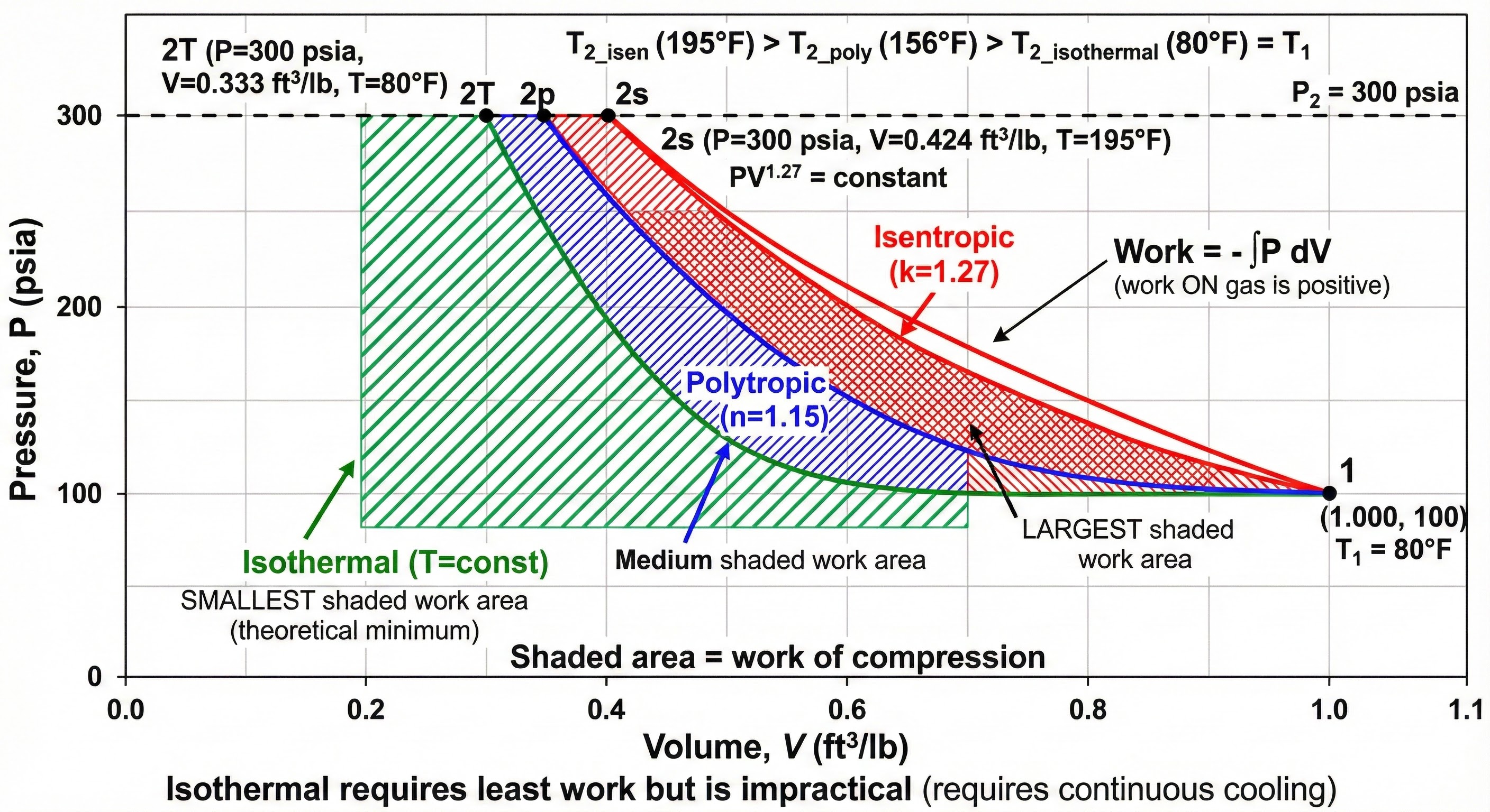
Two primary methods: isentropic (adiabatic) for reciprocating compressors and polytropic for centrifugal compressors per API 617.
Isentropic (Adiabatic) Method
Assumes reversible compression with no heat transfer. Preferred for reciprocating compressors.
Isentropic Head (GPSA Eq. 13-4):
H = (Z × R × T₁ / MW) × (k/(k-1)) × [(P₂/P₁)^((k-1)/k) - 1]
Where:
H = Head (ft·lbf/lb)
Z = Compressibility factor (0.85–1.0)
R = 1545.35 ft·lbf/(lbmol·°R)
T₁ = Suction temperature (°R = °F + 459.67)
MW = Molecular weight (lb/lbmol)
k = Specific heat ratio (Cp/Cv)
Brake Horsepower:
BHP = (ṁ × H) / (33,000 × η_isentropic)
Discharge Temperature (GPSA Eq. 13-18):
T₂_isentropic = T₁ × (P₂/P₁)^((k-1)/k)
T₂_actual = T₁ + (T₂_isentropic - T₁) / η
Keep T₂ < 300°F to avoid seal/material issues.
Polytropic Method
Accounts for non-ideal behavior. Preferred for centrifugal compressors per API 617.
Polytropic Exponent (GPSA Eq. 13-18):
η_p = [(k-1)/k] / [(n-1)/n]
Solving for n:
(n-1)/n = (k-1) / (k × η_p)
n = 1 / [1 - (k-1)/(k × η_p)]
Note: n > k always for real compression.
Polytropic Head:
H_p = (Z × R × T₁ / MW) × (n/(n-1)) × [(P₂/P₁)^((n-1)/n) - 1]
Gas Horsepower:
GHP = (ṁ × H_p) / 33,000
(Polytropic head already accounts for thermodynamic losses via n > k)
Discharge Temperature:
T₂ = T₁ × (P₂/P₁)^((n-1)/n)
P-V diagram comparing isentropic, polytropic, and isothermal compression paths.
Specific Heat Ratio (k) Values
Gas
k @ 60°F
k @ 150°F
MW
Notes
Natural Gas (SG=0.65)
1.27
1.24
18.9
Typical pipeline
Methane (CH₄)
1.31
1.28
16.04
Primary NG component
Ethane (C₂H₆)
1.19
1.16
30.07
Lower k → less power
Propane (C₃H₈)
1.13
1.10
44.10
Watch for liquids
CO₂
1.29
1.26
44.01
Z < 0.9 near critical
N₂ / Air
1.40
1.40
28
k ≈ constant
H₂
1.41
1.41
2.02
Very light; high head
3. Efficiency Factors
Efficiency accounts for irreversibilities that cause actual power to exceed ideal thermodynamic power.
Isentropic Efficiency:
η_isen = (Isentropic Work) / (Actual Shaft Work)
Typical: 0.70–0.88 depending on compressor type
Polytropic Efficiency:
η_poly = (Polytropic Work) / (Actual Work)
Typical: 0.75–0.85 for centrifugal
Key relationship:
For same machine: η_poly > η_isen (by 2-5%)
Compressor efficiency curve showing BEP, surge limit, and choke regions.
Operating Point
% Design Flow
Efficiency
Notes
Surge limit
50–70%
60–70%
Unstable; recycle required
BEP (design)
100%
78–85%
Maximum efficiency
Choke
115–125%
60–70%
Sonic velocity limit
Overall efficiency: η_overall = η_thermo × η_mech. For centrifugal with η_poly = 0.78 and η_mech = 0.97, overall = 0.76 (24% becomes heat).
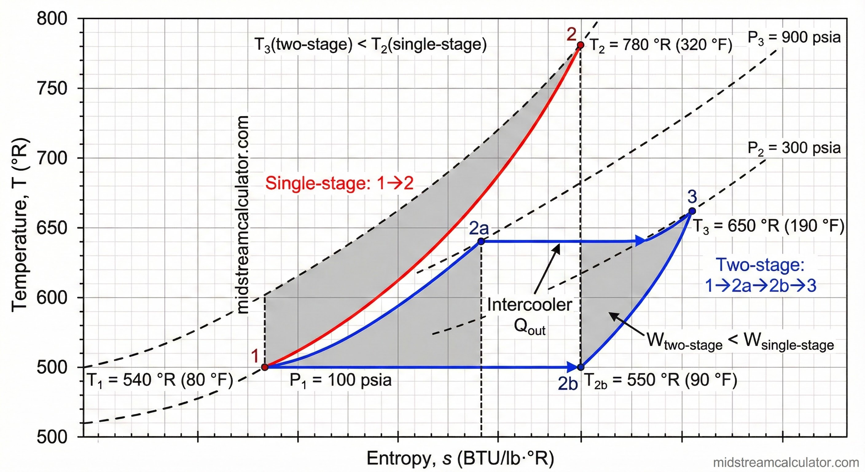
4. Multi-Stage Compression
When compression ratio exceeds 3.0–4.0, multi-stage with intercooling is more efficient.
Overall Ratio
Stages
Rationale
r ≤ 3.0
1
Optimal single-stage
3.0 < r ≤ 4.0
1 or 2
2-stage improves efficiency
4.0 < r ≤ 12
2
Two-stage + intercooling
12 < r ≤ 36
3
Three-stage + intercoolers
r > 36
4+
Four or more stages
Equal-Work Distribution:
For N stages with overall ratio R:
r_per_stage = R^(1/N)
Example: Two-Stage
P₁ = 100 psia, P₃ = 900 psia, R = 9.0
r = 9.0^(1/2) = 3.0 per stage
Interstage: P₂ = √(100 × 900) = 300 psia
Stage 1: 100 → 300 psia
Intercooler: cool to ~T₁
Stage 2: 300 → 900 psia
T-s diagram showing two-stage compression with intercooling vs single-stage.